


REPO Switch Installation
n Verify that all incoming line voltage (utility power)
and low voltage (control) circuits are de-energized, and
locked out before installing cables or making connec-
tions, whether in the junction box or to the
Symmetra
TM
Power Array.
n Always verify that all battery modules are removed
and all battery extension frames are disconnected from
the Power Array before installing any wiring to the
Power Array.
n Read this chapter completely before installing any
hardwiring connections to the Power Array.
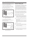
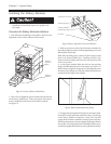
REPO Wiring Procedures
Remove the REPO wiring access panel to access the terminal
connections.
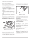
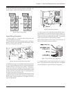
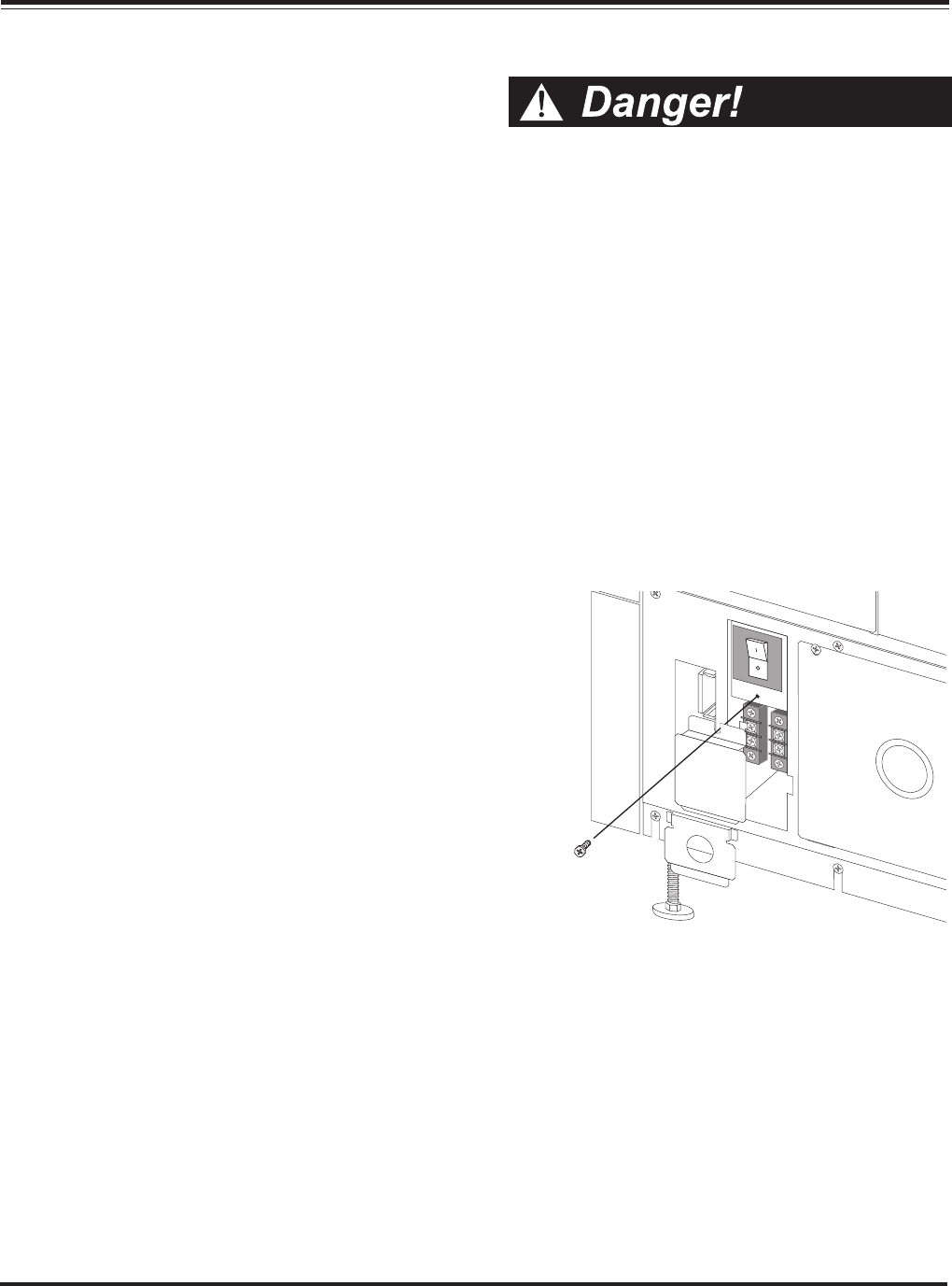
1. Refer to figure 4-13. Remove the screw holding the two
piece access panel at the rear of the Power Array. Remove the
panel. Set the screw and the panel aside temporarily.
Fig 4-13 Removal of REPO Wiring Panels
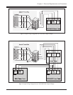
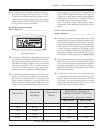
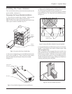
2. Refer to figures 4-14 and 4-15. Select the configuration
that matches the type of REPO switch that is to be installed.
Note: An existing jumper must be removed from the terminal
block if a 24Vdc REPO switch (Figure 4-15) is to be installed.
3. Extend the wiring from the switch to the Power Array. Strip
1/2” of insulation from the end of each of the incoming wires.
4. Feed the wires through the knockout in the access panel,
and install a strain relief (Romex) connector.
Chapter 4 - Electrical Requirements and Procedures
4-7
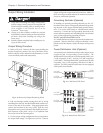
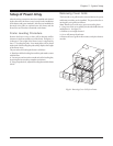
Remote Emergency Power
Off Switch
The Power Array can be de-energized with a remote emer-
gency power off (REPO) switch. REPO switches are com-
mon in computer rooms where, for safety reasons, power to
the loads must be quickly disconnected. The REPO switch
physically flips the system enable switch to “stand by” mode.
This cuts all power to the Power Array, and to the load equip-
ment. The system enable switch must be physically reset.
The REPO can be connected to either a switched, 24Vdc cir-
cuit, or a simple, contact closure.
REPO Specifications
The REPO circuit is considered a Class 2 and SELV circuit.
SELV is an acronym for “Safety Extra Low Voltage.” SELV is
a common term in Europe and IEC standards. A SELV cir-
cuit is isolated from primary circuitry through an isolating
transformer and designed so that under normal conditions,
the voltage is limited to 42.4 Vpeak or 60 Vdc.
A Class 2 Circuit is a common term in North America and in
UL and CSA standards. It is defined in the Canadian Electri-
cal Code (C22.1, Section 16), and the National Electrical Code
(NFPA 70, Article 725).
SELV and Class 2 circuits must be isolated from all primary
circuitry. Do not connect any circuit to the EPO terminal
block unless it can be confirmed that the circuit is SELV or
Class 2. If there is a question, use a contact closure switch.
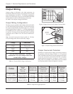
Cable Specifications
The cable that connects Symmetra
TM
to the Emergency Power
Off switch should be UL Listed, type:
CL2 - Class 2 cable for general purpose use; or
CL2P - Plenum cable for use in ducts, plenums and other
space used for environmental air; or
CL2R - Riser cable for use in a vertical run in a shaft or from
floor to floor; or
CL2X - Limited Use cable for use in dwellings and for use in
raceway.
For installation in Canada, the cable should be CSA Certi-
fied, type ELC (Extra-Low-Voltage Control Cable).