


output wiring to the output terminal connections. Make sure
there are no loose strands and that the terminal connection
screws are sufficiently tightened.
Grounding Electrode (Optional)
If installing an optional grounding electrode, use the 1/2”
knockout in the output wiring panel, and attach the ground-
ing electrode to the output terminal block ground connec-
tion. (Use a strain relief clamp, or a flexible metal conduit
connector.) Connect the local grounding electrode to the
nearest effective ground, such as building steel, a metal water
pipe, or other appropriate grounding structure.
See NEC code 250-26 and Table 310-16.
4. Carefully fold excess output wiring into the terminal com-
partment. After the electrical wiring test/checklist is com-
pleted (end of this chapter), replace the output wiring access
panels.
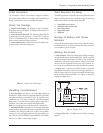
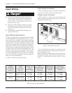
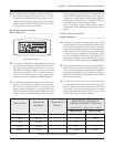
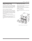
Power Distribution Units (Optional)
An optional power distribution unit provides output power
receptacles and corresponding circuit breakers. The
MiniFrame PDU provides one L6-30R receptacle (208V), two
5-15R receptacles (120V), and two L14-30R receptacles
(120V/240V). The MasterFrame PDU provides three L6-30R
receptacles, four 5-15R receptacles, and three L14-30R re-
ceptacles. The PDU panel for both frame sizes are equipped
with a panel circuit breaker.
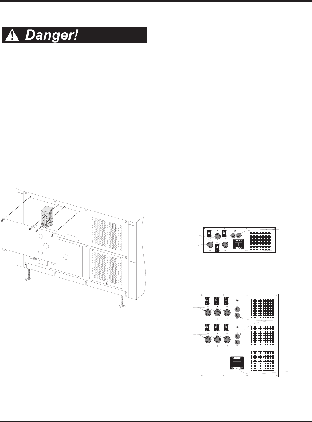
Fig. 4-11 MiniFrame PDU Panel
Fig. 4-12 MasterFrame PDU Panel
4-6
Chapter 4 - Electrical Requirements and Procedures
Output Wiring Installation
n Verify that all incoming line voltage (utility power)
and low voltage (control) circuits are de-energized, and
locked out before installing cables or making connec-
tions, whether in the junction box or to the
Symmetra
TM
Power Array.
n Always verify that all battery modules are removed
and all battery extension frames are disconnected from
the Power Array before installing any wiring to the
Power Array.
n Read this chapter completely before installing any wir-
ing to the Power Array.
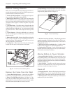
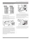
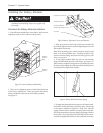
Output Wiring Procedure
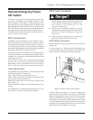
1. Refer to Fig 4-10. Remove the four screws holding the
output wiring entry panels to the rear of the Power Array.
Remove only the screws indicated in the illustration. Set the
screws and both panels aside temporarily.
Fig. 4-10 Removal of Output Hardwiring Panels
2. Pull wire through conduit, leaving about 20” of wiring
extending from the end. Install a flexible metal conduit con-
nector to the end of the conduit. Using appropriate tools,
remove the knockout in the entry panel. Feed the wires
through the entry panel, and attach the flexible metal con-
duit connector to the panel. Strip 1/2” of insulation from
the end of each of the incoming wires.
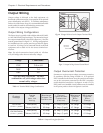
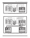
3. Use the output wiring configuration that corresponds to
the output load voltage. See figures 4-8 and 4-9. Connect
L14-30R
Receptacles
L6-30R
Receptacles
5-15R
Receptacles
Panel
Circuit
Breaker
L6-30R
Receptacles
L14-30R
Receptacles
5-15R
Receptacles
Panel Circuit
Breaker