


Power Module Replacement
The following section provides the procedure for replacing a
power module.
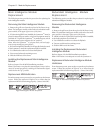
Removing the Power Module
1. Remove the grill cover from in front of the module to be
replaced. Note that the module bays are labelled to corre-
spond with the PowerView display.
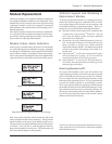
2. If replacing a non-redundant power module, or if the power
module to be replaced is the only power module present, the
Symmetra
TM
must be placed in manual bypass mode, or the
load equipment must be switched off. To place the Symmetra
TM
in manual bypass, switch the maintenance bypass switch to
the “on” position.
Note: When the Symmetra
TM
is in bypass mode, the load equip-
ment is unprotected from power failure.
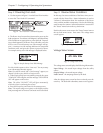
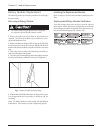
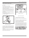
3. Use a flathead screwdriver to release the fliplatch from the
power module. See figure 8-7.
Fig 8-7 Release the Flip Latch
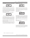
4. Note the two drop lock seating tabs at the front of the
power module. See Figure 8-8. These are designed to hold the
module firmly in the Power Array frame. When removing a
failed power module, lift the front of the module slightly to
release the drop lock seating tabs, and then pull the module
from the bay.
5. Remove the power module from the frame. If the module
has failed and needs to be disposed of, return it to the appro-
priate service provider, or directly to APC.
Chapter 8 - Module Replacement
8-3
Fig 8-8 Drop Lock Seating Tabs
Installing the Replacement Module
Refer to chapter 5 for the power module installation proce-
dure.
Note: If Symmetra
TM
was placed in manual bypass in step 2
above, return to normal operation by switching the mainte-
nance bypass switch back to the “off” position.
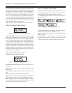
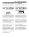
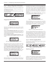
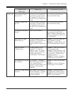
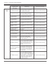
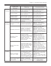
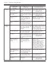
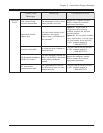
Replacement Module Verification
From the startup screen, press any key to open the top level
menu screen. Follow the sequence in figure 8-9 to insure that
the new module is functioning properly. Note that the up/
down cursor appears, and the information for each power
module is reviewed by pressing the up or down navigation key.
Make sure all power modules display a status of “On & OK.”
Fig 8-9 Power Module Verification
Drop Lock
Seating Tabs