


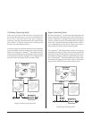
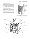
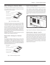

Main Intelligence Module (MIM)
The MIM is the onboard computer for the Power Array sys-
tem. It gathers and processes data, including monitoring the
condition of each of the modules.
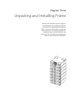
Fig 1-6 Main Intelligence Module
The PowerView functions as the user interface for the MIM,
and is used to access data, and to configure the system. When
a redundant intelligence module is installed and functioning,
the main intelligence module can be replaced without placing
the load at risk. The main intelligence module also communi-
cates to an external battery frame (if present). The main intel-
ligence module and the redundant intelligence module are fac-
tory installed into custom racks that are built into the bay at
the upper right of the frame.
Important: The MIM is always installed in the bottom rack, and
the RIM is always installed in the top rack.
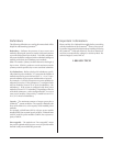
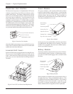
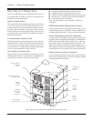
Redundant Intelligence Module
(RIM)
The redundant intelligence module is a back-up version of the
main intelligence module. It provides redundancy in the event
of a MIM failure, or while a MIM is being replaced. If a func-
tioning MIM is present, the RIM can be removed and replaced
without placing the load at risk. The condition of the RIM can
be determined with the PowerView.
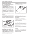
Fig 1-7 Redundant Intelligence Module
Chapter 1 - Physical Representation
1-3
Retaining Screw
Positioning Handle
Installation Rail
Blind Mating
Connector
Flip Latch Micro Switch
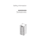
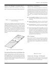
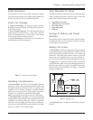
Input Circuit Breaker
The input circuit breaker protects the Power Array from ex-
treme overloads. When switched to “stand by” the Power
Array is disconnected from incoming utility voltage. When
switched to the “on” position, power flows from the utility
source into the Power Array. Under normal operating condi-
tions, the input circuit breaker always remains in the “on” po-
sition.
Fig 1-8 Input Circuit Breaker & Maintenance Bypass Switch
Maintenance Bypass Switch
When switched to the “on” position, the maintenance bypass
switch bypasses the Power Array, and causes the load equip-
ment to be powered directly from utility power. When it is
switched to the “off” position, utility power flows into the
Power Array, and conditioned power is delivered to the load
equipment. The load equipment is unprotected when the main-
tenance bypass switch is in the “on” position. Under normal
operating conditions, the maintenace bypass switch always
remains in the “off” position.
Retaining Screw
Positioning Handle
Installation Rail
Blind Mating
Connector
Flip Latch Micro Switch