


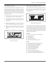
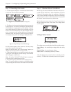
Step 7: Review Diagnostic Information
The PowerView allows the user to access an extensive set of
self-diagnostics information. Follow this procedure to re-
view the diagnostic screens.
The following sequence on the PowerView opens the diag-
nostics menu screen:
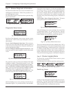
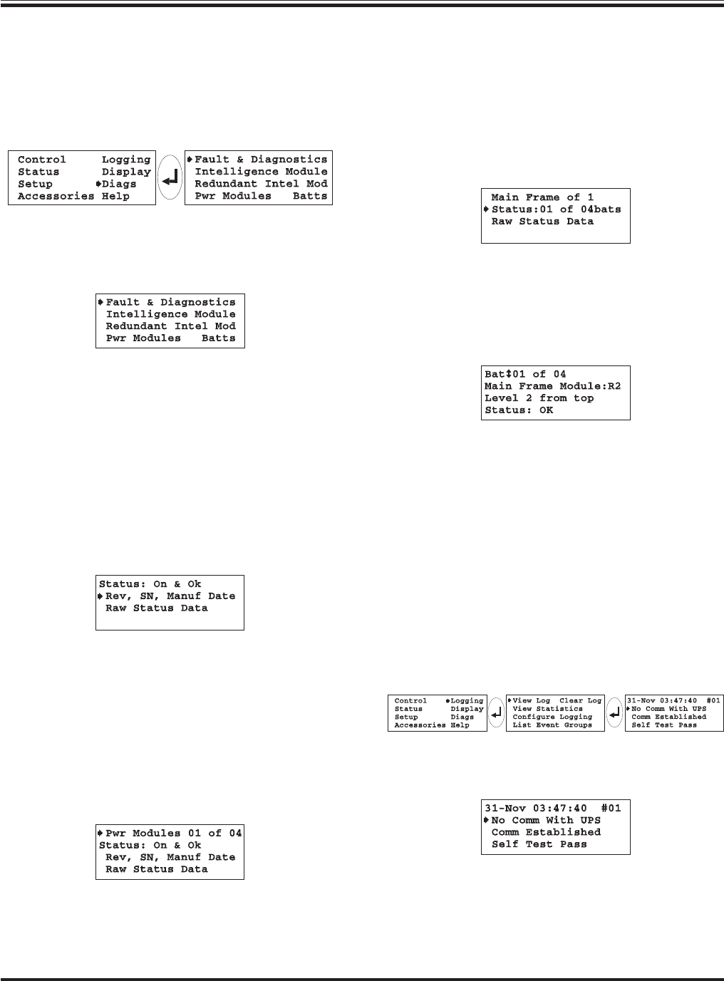
Fig 7-18 Opening the Diagnostics Menu Screen
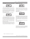
Diagnostics Menu Screen
Fig 7-19 Diagnostics Menu Screen
Each line of the diagnostics menu screen contains a menu
selection item. Each of these open subsequent screens as
shown below.
Line #1: Fault & Diagnostics Menu Item - This screen pro-
vides an overview of any faults detected within the system. If
a fault is detected, the PowerView will specify which type of
system component has failed.
Line #2: Intelligence Module Diagnostic Menu Item - This
menu item opens the main intelligence module information
screen.
Fig 7-20 Intelligence Module Information Screen
The status line at the top of this screen indicates if the main
intelligence module is functioning properly or not. This
screen also provides detailed information about the MIM.
Line #3: Redundant Intelligence Module Diagnostic Menu
Item - This screen opens the redundant intelligence module
information screen. It appears the same as figure 7-20.
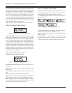
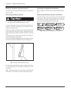
Line #4 (left): Power Module Diagnostic Menu Item - This
menu item opens the power module information screen.
Fig 7-21 Power Module Information Screen
With the flashing arrow cursor pointing at the first line (as
illustrated in figure 7-21), press the enter key. Note the flash-
Chapter 7 - Configuring & Operating the Symmetra
TM
7-6
ing up/down arrow appears. Use the arrow navigation keys
to scroll up or down. The status of each module will appear
one at a time. In the event of a power module failure, use
this screen to identify which power module has failed. Use
this screen to confirm that a new module is recognized by
the Power Array, and is functioning properly. (Procedure in
chapter 8.)
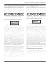
Line #4 (right): Battery Diagnostic Menu Item - This menu
item opens the battery module information screen.
Fig 7-22 Battery Module Information Screen
With the flashing arrow cursor pointing at the second line
(as illustrated in figure 7-22), press the enter key. Note the
flashing up/down arrow appears. The status screen for the
battery module in the top battery module bay appears:
Fig 7-23 Top Battery Module Status Screen
This screen indicates that the battery module in bay “R2” is
functioning properly. Use the arrow navigation keys to scroll
through all of the battery module status screens. In the event
of a battery module failure, use this screen to identify the
battery module that has failed. After a battery module is re-
placed, confirm the new module is recognized by the Power
Array, and is functioning properly. (Procedure in chapter 8.)
Step 8: Review Logging Menu
The PowerView records the most recent 64 user or power
events in an electronic log.
The following screen sequence opens the event log screen:
Fig 7-24 Open the Event Log Sequence
Event Log Screen
Fig 7-25 Event Log Screen
Scroll up or down through the log items using the arrow navi-
gation keys. The time, date and the number of the selcted
log item is displayed on the top line. For more information
about a log item, select it, and press the enter key.