


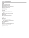
Step 4: Perform a Self Test
A Power Array self test measures system performance by se-
quentially placing each power module on battery, and then
briefly placing all of the power modules on battery.
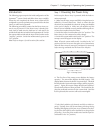
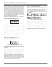
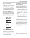
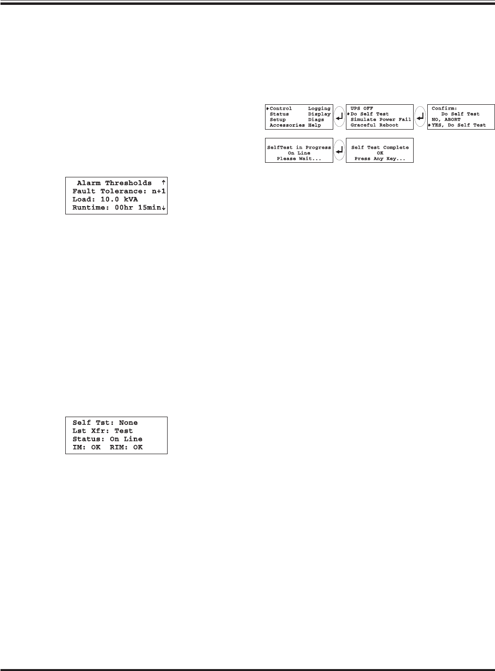
1. The following sequence on the PowerView will initiate a
system self test:
Fig 7-13 Initiate a Self Test Sequence
2. The PowerView displays the message "Self Test In Progress"
while the Power Array system performs the test.
Note: The Power Array will make a series of clicking sounds
during a self test.
3. The PowerView will either report that the self test was
completed with no errors, or will report any failures detected.
4. Press the escape key and return to the startup screen.
The power status screen also displays the actual level of fault
tolerance, the number of power modules in the frame, and
the number of “bad” power modules. The actual fault toler-
ance indicates the number of functioning power modules in
the Power Array, minus the number required to power the
load. (i.e., If a load is 6kVA, two modules are required. If
there are five modules installed, the fault tolerance would read
N+3.) Use this screen to check the status of the power mod-
ules. After this screen has been reviewed, press enter. The
alarm threshold status screen appears.
Note: If a power module is diagnosed as “bad,” see chapter 8.
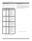
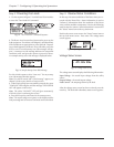
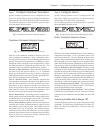
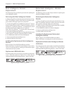
Alarm Threshold Status Screen
Fig 7-11 Sample Alarm Threshold Status Screen
Alarm Thresholds - The alarm threshold status screen dis-
plays the user-defined fault tolerance threshold. An audible
alarm will sound if the level of redundancy drops below this
level. This screen also displays a user specified load thresh-
old. An audible alarm will sound if the attached load ex-
ceeds this threshold. Finally, the run time alarm threshold is
displayed. An audible alarm will sound if the predicted run
time becomes less than this threshold (either because of loss
of battery capacity, or increased load). After the alarm thresh-
old status screen has been reviewed, press enter. The miscel-
laneous status screen appears.
Note: Alarm thresholds will be set in Step 4.
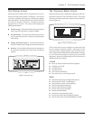
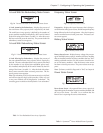
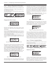
Miscellaneous Status Screen
Fig 7-12 Sample Miscellaneous Status Screen
The Miscellaneous Status Screen - displays the following in-
formation:
Self Test - the results of the last self test perfomed by the
Power Array.
Last transfer - displays the reason for the last transfer to bat-
tery.
Status - identifies the current mode of operation.
Note: See the “Introduction” for details about operating modes.
IM - displays the status of the main intelligence module.
RIM - displays status of the redundant intelligence module.
The miscellaneous status screen is the final status screen. Press
the Escape key to return to the startup screen.
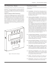
Chapter 7 - Configuring & Operating the Symmetra
TM
7-4