


Chapter 5 - System Setup
5-4
Installing the Main Intelligence
Module (MIM)
The main intelligence module is factory installed. The follow-
ing procedures is provided in the event that the module is
removed, or needs to be replaced.
Procedure for Main Intelligence Module
(MIM) Installation
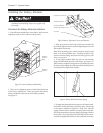
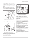
1. The main intelligence module fits into a bay at the upper
right corner of the Power Array frame.
Note: The main intelligence module is always installed in the
bottom of this bay, and the redundant intelligence module is
always installed in the top.
2. Carefully align the installation rail on the MIM, with the
track that runs along the inside of the bay.
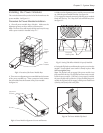
4. Slide the MIM into the bay.
5. Tighten the two retaining screws. Do not overtighten.
6. Swing the flip latch into place, and tighten the screw. Do not
overtighten.
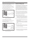
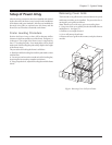
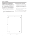
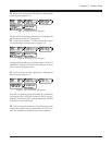
Fig 5-9 Location of the MIM and RIM
Redundant
Intelligence
Module
(RIM)
Main
Intelligence
Module
(MIM)
Installing the Redundant
Intelligence Module (RIM)
The redundant intelligence module is factory installed. The
following procedures is provided in the event that the module
is removed, or needs to be replaced.
Procedure for Redundant Intelligence
Module (RIM) Installation
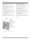
1. The redundant intelligence module fits into a bay at the
upper right corner of the Power Array frame.
Note: The redundant intelligence module is always installed in
the top of this bay, and the main intelligence module is always
installed in the bottom.
2. Carefully align the installation rail on the RIM, with the
track that runs along the inside of the bay.
4. Slide the RIM into the bay.
5. Tighten the two retaining screws. Do not overtighten.
6. Swing the flip latch into place, and tighten the screw. Do not
overtighten.