


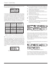

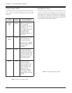
q 6. Press the down arrow key to scroll to the power mod-
ule status screen. See figure 5-19.
Fig 5-19 Power Status Screen
Verfiy that the number of power modules reported (3 in figure
5-19) is the same as the actual number of power modules that
are installed. Verify that the number of “bad” modules re-
ported is zero. The first line of the power status screen dis-
plays the reported capacity of the Symmetra
TM
. The reported
capacity is dependent upon the number of power modules
installed, and the size of the frame. Use table 5-1 to confirm
that the PowerView is reporting the correct information.
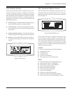
rebmuN
rewoPfo
seludoM
detropeR
niyticapaC
emarFiniM
detropeR
niyticapaC
emarFretsaM
1AVk4AVk4
2AVk8AVk8
3AVk8AVk21
4a/nAVk61
5a/nAVk61
Table 5-1 Symmetra
TM
Power Module/Frame Capacities
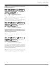
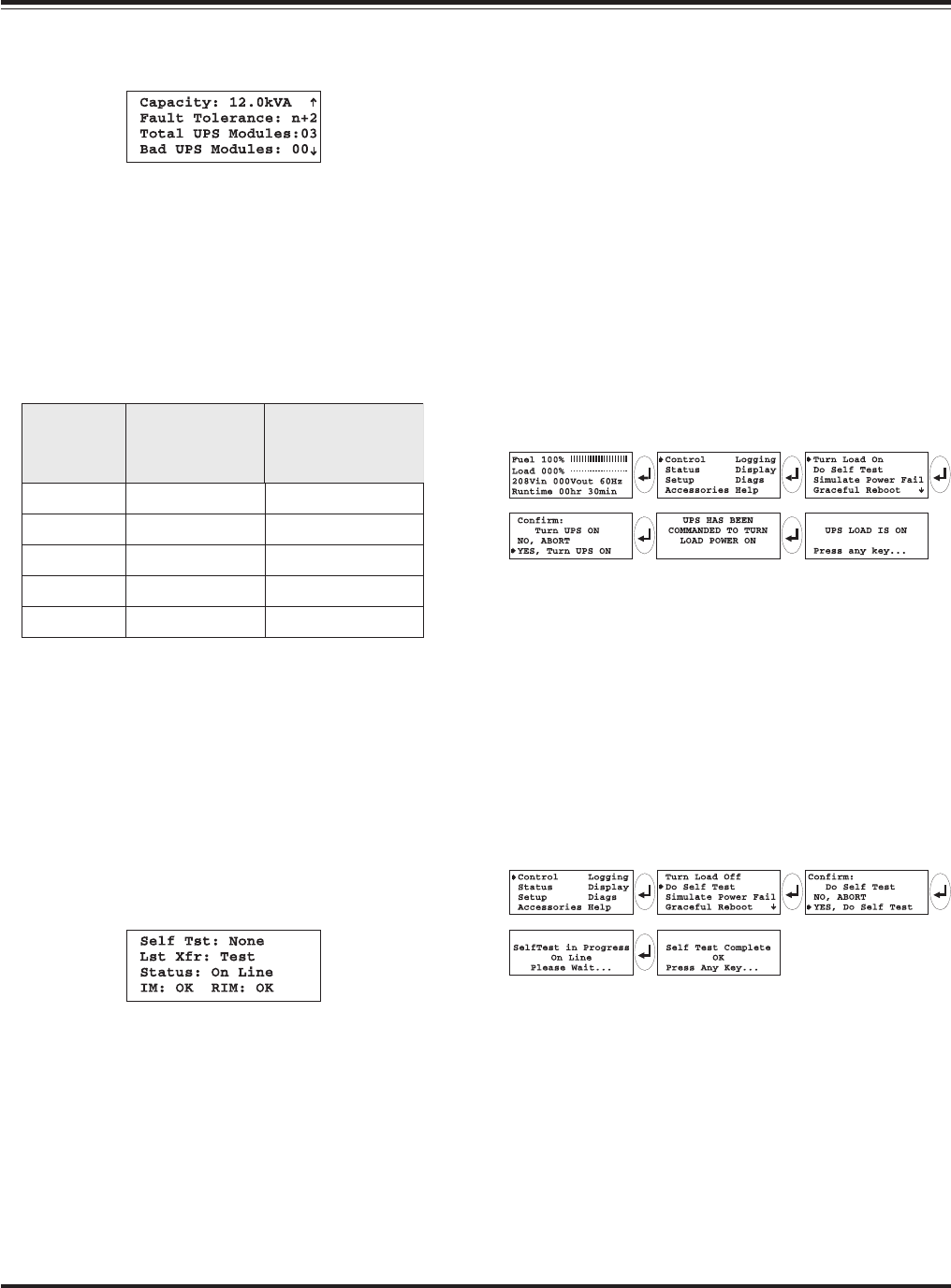
q 7. Press the down arrow key to scroll to the miscellaneous
status screen. See figure 5-20. The bottom line indicates the
status of the MIM and RIM. The sample screen in figure 5-20
indicates that both are installed and functioning properly (OK).
If a module is not installed, the status screen will display the
word “NONE.” Confirm that the status of the MIM and RIM
as indicated by this screen conforms to the actual installation
of those modules. Use the ESC key to return to the startup
screen.
Fig 5-20 Miscellaneous Status Screen
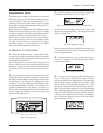
q 8. Use the following steps to deliver output voltage to the
load equipment. See figure 5-21 for the screen sequence.
n Press the ESC navigation key on the PowerView display
until the startup screen appears.
n Press the ESC key to display the top level menu.
n Press the down arrow navigation key, until the cursor is
pointing to “Control.”
n Press the “enter” navigation key.
n Press the down arrow navigation key, until the cursor is
pointing to “Turn Load ON.”
n Press the “enter” navigation key.
n Confirm that you want to turn the load on, by selecting
“YES, Turn UPS ON”
n Several other over-ride messages may appear, depending
on the system configuration. Select “start now” for any
of these startup over-ride messages.
Fig 5-21 Power The Load Sequence
After several seconds, the PowerView display should report
that the “UPS LOAD IS ON.” Press the ESC key to return to the
startup screen. Confirm that output voltage is present, and
that the Load On LED is glowing.
Note: The Bypass LED may flash on briefly, and the On Battery
LED may light for 20-30 seconds if the system is configured for
“self test at power on.”
q 9. Perform a self test by following the screen sequence in
figure 5-22.
Fig 5-22 Initiate a Self Test Sequence
The On Battery LED should glow for approximately 30 sec-
onds. A message will appear on the display indicating that a
self test is in progress. When the “Self Test Complete” message
appears, press any key to return to the startup screen.
5-8
Chapter 5 - System Setup