


Installing the PowerView Interface
An 18” RJ45 cable (supplied) is provided in bay “L1.” It is used
to connect the PowerView to the Power Array. Use the follow-
ing procedure to install the PowerView interface to the front of
the frame.
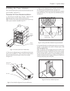
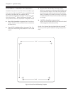
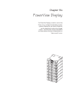
1. Remove the cover grill from the top level of the frame.
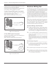
2. Feed the end of the RJ45 cable through the center slot of the
top cover grill, and replace the cover grill onto the frame. See
figure 5-10.
Fig 5-10 PowerView Cable Through Cover Grill
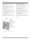
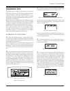
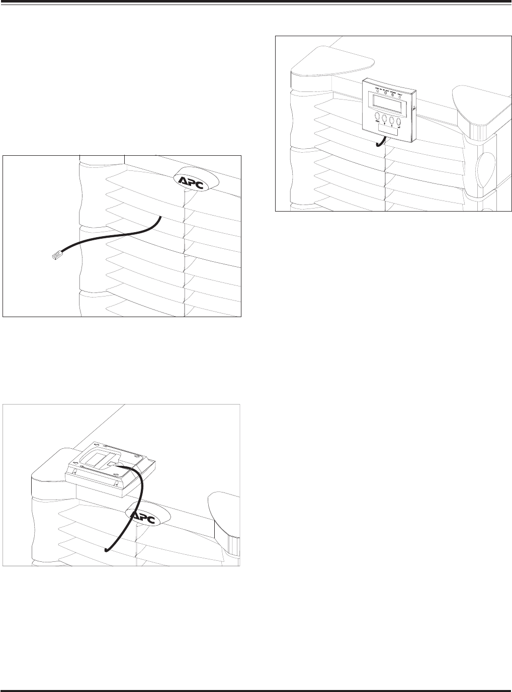
3. Connect the RJ45 plug into the receptacle on the back of the
PowerView as shown in figure 5-11.
Fig 5-11 Attaching the Cable to the PowerView
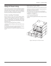
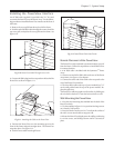
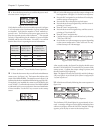
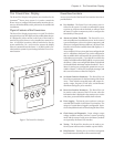
5. Position the PowerView over the mounting post on the
front of the frame, and push straight down. The PowerView
snaps into place. See figure 5-12.
6. Tuck the excess cable into the grill cover.
Fig 5-12 Install PowerView Onto Frame
Remote Placement of the PowerView
The PowerView can be mounted at a remote location, up to 20’
from the frame. Follow the steps below to install PowerView
in a remote location.
1. A 20’ RJ45 cable is included with the Symmetra
TM
Power
Array.
2. Connect one end of the RJ45 cable to the rear of the Power
Array frame. See figure 1-8 in chapter 1.
3. Connect the other end of the cable to the receptacle at the
rear of the PowerView interface.
4. The short RJ45 cable at the top of power module bay “L1”
can be safely tucked onto the top of the power module. Re-
place the grill cover.
The PowerView will sit upright on a flat surface, by folding out
the wire bail on the back. It can also be mounted to a wall.
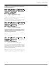
Wall Mounting the PowerView
1. Note the four mounting slots molded into the back of the
PowerView body.
2. Use the template in figure 5-13 to position four large screws
on a clean dry wall surface.
3. Leave the head of each screw 5/16" out from the surface of
the wall. Screws must be able to support 15lb.
4. Mount the PowerView display onto the wall by positioning
it over the screws, and sliding it down until it is securely in
place.
Chapter 5 - System Setup
5-5