


4-8
Chapter 4 - Electrical Requirements and Procedures
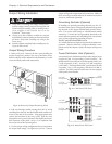
5. Make sure there are no loose strands and that the terminal
connection screws are sufficiently tightened.
6. After the electrical wiring test/checklist is completed (end
of this chapter), replace the REPO access panel.
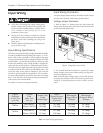
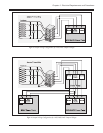
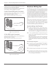
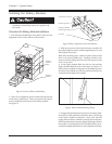
Contact Closure REPO Switch Connection
Connect the contact closure REPO wiring to the terminal
block as illustrated in figure 4-14 below.
Note: The factory installed jumper remains as shown.
Fig 4-14 Dry Contact Switch
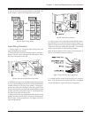
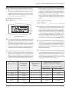
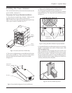
24 Vdc REPO Switch Connection
Connect the 24Vdc REPO wiring to the terminal block as
illustrated in figure 4-15 below.
Note: The factory installed jumper must be removed.
Fig 4-15 24Vdc EPO Switch
24Vdc
Power
Source
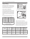
Electrical Wiring Test
The following test procedure will ensure the Power Array has
been correctly hardwired. It is intended that the licenced
electrician who installed Power Array will perform this test.
A true RMS voltmeter is required for this procedure.
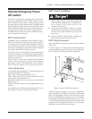
Before this test can be conducted, the main intelligence mod-
ule (MIM) must be installed, and the PowerView display must
be connected to the Power Array. Refer to chapter 5 for pro-
cedures to install the MIM and the PowerView. The power
and battery modules need not be installed to perform this
test.
Note: This test is intended to verify the electrical connection to
the Power Array, not to verify it’s operation or explain it’s us-
age. In this procedure, you will be instructed to ignore
PowerView messages, etc. Refer to chapters 6 & 7 for detailed
information about the operation of the Power Array.
Electrical Wiring Test/Checklist
q 1. Make sure all three switches - system enable, mainte-
nance bypass, and input circuit breaker are in the “off”
or “stand by” position. Make sure all load equipment is
either turned off, or is unplugged from the Power Array.
q 2. Use a true RMS voltmeter to measure the input AC
voltage at the terminal connections at the rear of the
frame (bottom level).
Note: If input voltage is less than 156Vrms or greater than
276Vrms, check input wiring for errors. DO NOT PRO-
CEED UNTIL THE INPUT VOLTAGE IS WITHIN THIS
RANGE.
Record the input voltage here: ____________________
q 3. Check for proper ground installation. If available, a
ground ohmmeter should be used. Otherwise, check
for continuity to building ground.
q 4. Switch the input circuit breaker to the “on” position.
q 5. Switch the system enable switch to the “on” position.
Note: The Power Array may make a series of clicking sounds
as it runs through an initial self test.
Jumper Installed