


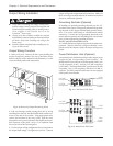

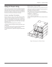
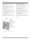


Installing the Power Modules
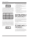
The vertical column of bays at the left of the frame house the
power modules. See Figure 5-5.
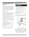
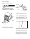
Procedure for Power Module Installation
1. Clear all power module bays of debris. Make sure the
alignment grooves are clear, and free of obstruction.
Note: The PowerView cable must be held up and out of the way,
while a power module is installed in bay “L1.”
Fig 5-5 Location of the Power Module Bays
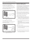
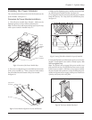
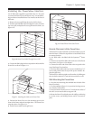
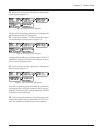
2. There are two alignment grooves molded into the bottom
of the power module bay. These correspond with runners
that are molded into the bottom of the power module.
See figure 5-6.
Fig 5-6 Power Module Alignment Grooves and Runners
4. Make sure the alignment grooves and the runners are lined
up. Slide the power module into bay. See figure 5-6.
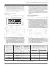
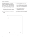
5. To engage the internal connector, slide the power module
firmly into the bay. The “drop lock” tabs will fall into place.
See figure 5-7.
Fig 5-7 Seating Tabs When Module is Properly Installed.
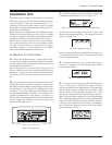
6. Swing the flip latch up and fasten the captive screw into the
module. Gently tighten screw until it is firmly in place. DO
NOT overtighten screw.
Note: The flip latch will not engage if the power module is not
fully seated into the bay. The flip latch activates a micro switch
inside the power module. If the latch is not properly installed,
the power module will not function. If after installing the power
module, the flip latch will not engage, pull the power module out
of the bay, and firmly slide it into place.
Fig 5-8 The Power Module Flip Latch
Runners
Alignment
Grooves
Drop Lock
Seating Tabs
Chapter 5 - System Setup
5-3
Power
Module
Bays
Power
Module