


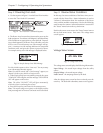
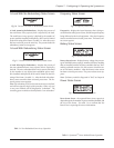
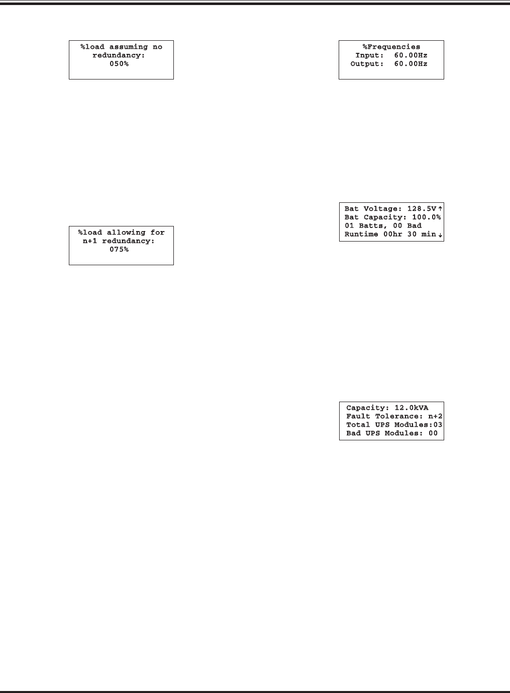
% Load With No Redundancy Status Screen
Fig 7-6 Percent Load With No Redundancy Status Screen
% Load Assuming No Redundancy - displays the percent of
the total Power Array capacity that is required by the load.
The total Power Array capacity is defined by the number of
power modules installed, multiplied by 4kVA and is limited
by the kVA rating of the frame. See table 7-2. After this screen
has been reviewed, press the enter key. The percent load with
redundancy status screen appears.
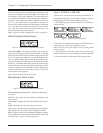
% Load With Redundancy Status Screen
Fig 7-7 Percent Load With Redundancy Status Screen
% Load Allowing For Redundancy - displays the percent of
the non-redundant Power Array capacity that is required by
the load. The non-redundant Power Array capacity is defined
by the number of user defined non-redundant power mod-
ules installed, multiplied by 4kVA and is limited by the kVA
rating of the frame. See table 7-1. After the load with redun-
dancy status screen has been reviewed, press enter. The fre-
quency status screen appears.
Note: The redundancy level for this measurement is user defined,
and will be assigned in Step 6 of this procedure. Either zero, one
or two power modules will be designated as “redundant.” The
remaining power modules are then defined as “non-redundant.”
Table 7-1 Non-Redundant Power Array Capacities
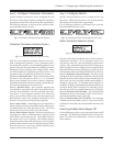
Frequency Status Screen
Fig 7-8 Frequency Status Screen
Frequencies - displays the input frequency that is being re-
ceived from the utility power source, and the output frequency
being delivered to the load equipment. After the frequency
status screen has been reviewed, press enter. The battery sta-
tus screen appears.
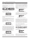
Battery Status Screen
Fig 7-9 Battery Status Screen
Battery Status Screen - displays battery voltage, the percent-
age of available battery capacity, number of battery modules
that are installed, number of battery modules that are “bad”
and the predicted run time. Use this screen to check the sta-
tus of the battery modules. After the battery status screen
has been reviewed, press enter. The power status screen ap-
pears.
Note: If a battery module is diagnosed as “bad,” see chapter 8.
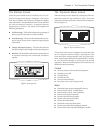
Power Status Screen
Fig 7-10 Sample Power Status Screen
Power Status Screen - the reported Power Array capacity is
dependent upon the number of power modules installed, and
the size of the frame. Use table 7-2 to confirm that the
PowerView is reporting the correct information.
Table 7-2 Symmetra
TM
Power Module/Frame Capacities
Chapter 7 - Configuring & Operating the Symmetra
TM
7-3