


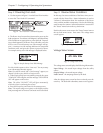
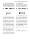
Step 3: Review Status Conditions
In this step, the status conditions of the Power Array are ac-
cessed with the PowerView. Status information is used as
“reference” information about the condition of the Power
Array, and the modular components. Review the following
status screens for content. Status information is accessed via
the “Status” menu item on the top level menu.
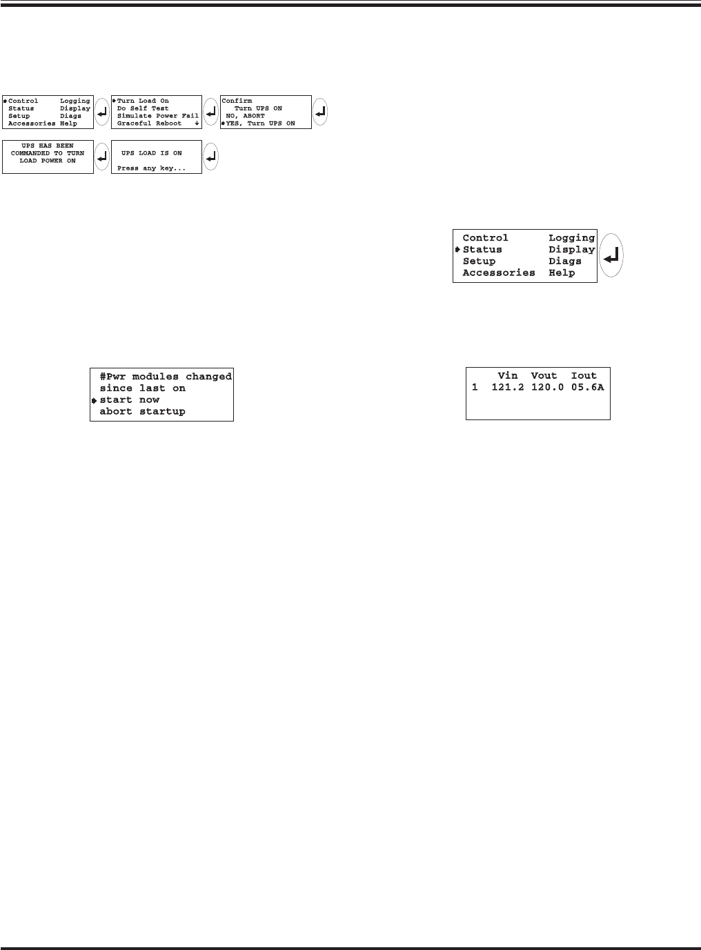
Position the arrow cursor next to the “Status” menu item on
the top level menu screen. Press enter. The voltage status
screen appears.
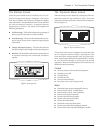
Fig 7-4 Opening the Status Menu Item
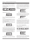
Voltage Status Screen
Fig 7-5 Voltage Status Screen
The voltage status screen displays the following information:
Input Voltage - the actual input voltage from the utility
source.
Output Voltage - the actual output voltage.
Load Current - the amperage drawn by the load.
After the voltage status screen has been reviewed, press the
enter key. The load with redundancy status screen appears.
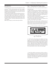
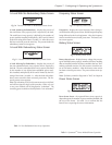
Step 2: Powering the Loads
1. Use the sequence in figure 7-2 on the PowerView interface
to enter the “Turn Load On” command.
Fig 7-2 “Turn Load On” Command Sequence
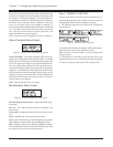
2. The Power Array has now been instructed to power up the
load equipment. It conducts a self diagnosis, and determines
if the conditions are appropriate to power the load. Depend-
ing on the diagnostics, the Power Array will either power the
load, or one of several startup over-ride messages will ap-
pear. A startup over-ride message indicates an exceptional
condition exists, and gives the option to proceed or abort.
An example startup over-ride message is displayed below:
Fig 7-3 Sample Startup Over-Ride Message
For this initial sequence, select “start now” for any startup
over-ride message that may appear.
Note: If an alarm sounds, and a “fault message” appears, see
chapter 9 for the cause, and the corrective action.
3. When the load has been successfully powered, the green
“LOAD ON” LED will glow, and the message “UPS LOAD IS
ON” will appear on the screen.
Note: The yellow "ON BATT" LED will glow momentarily,
while the system is conducting the self test.
4. Press the Escape key and return to the startup screen.
Note: The output voltage now registers on the display, and the
load percentage and run time are now based on the actual load.
Chapter 7 - Configuring & Operating the Symmetra
TM
7-2