


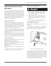


Installing the Battery Modules
n Each battery module weighs 60 lb. Battery module
installation and handling requires two people to lift
the module.
Procedure for Battery Module Installation
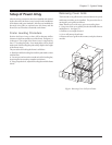
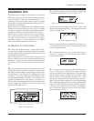
1. Clear all battery module bays of any debris. Make sure the
alignment tracks are clear, and free of obstruction.
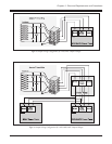
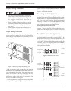
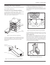
Fig 5-2 Location of Battery Module Bays
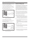
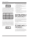
2. There are two alignment grooves molded into the bottom
of the battery module bay. These correspond with runners
that are molded into the bottom of the battery module.
See figure 5-3.
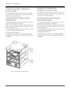
Fig 5-3 Battery Alignment Grooves and Runners
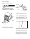
3. With one person on either side of the battery module, lift
the module, align the runners with the alignment grooves, and
slide module into the bay.
Note: When installing power or battery modules, always install
them in the lowest available bays. Installing modules in this
manner minimizes lifting, and lowers the center of gravity of the
Power Array system.
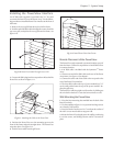
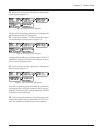
4. As the battery module slides into the bay, the retaining
flange will fall behind the notch in the frame. See figure 5-4.
When a battery module is being removed, this flange prevents
the battery from falling out of the bay until both people have
assumed the full weight of the module.
Fig 5-4 Battery Module Retaining Flange
5. To engage the internal electrical connector, the battery mod-
ule must be swiftly and firmly pushed into place. The design
of the battery module incorporates a “drop lock” that will
engage when the battery module is properly seated in the bay.
If the internal connector does not engage, a slight tug will move
the module. If it is locked, the battery module will not move,
and must be slightly lifted before it can be pulled from the bay.
Battery
Module
Bays
Battery
Module
Runners
Battery Module
Retaining Flange
Retaining Notch
Alignment Grooves
Chapter 5 - System Setup
5-2