


8-4
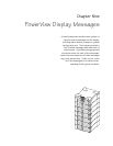
Chapter 8 - Module Replacement
Main Intelligence Module
Replacement
The following section provides the procedure for replacing the
main intelligence module.
Removing the Main Intelligence Module
1. Remove the grill cover from the top level of the Power Array.
Note: The intelligence module resides under the redundant intelli-
gence module, in the upper right corner of the frame.
2. If a functioning RIM is not installed, the Symmetra
TM
must be
placed in manual bypass mode, or the load equipment must be
switched off. To place the Symmetra
TM
in manual bypass, switch
the maintenance bypass switch to the “on” position.
Note: When the Symmetra
TM
is in bypass mode, the load equip-
ment is unprotected from power failure.
3. If a functioning RIM is installed, it will provide limited control
of the Symmetra
TM
until the replacement MIM is installed.
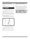
4. Use a flathead screwdriver to release the fliplatch.
5. Unscrew and release the retaining screws.
6. Slide the MIM out of the frame.
Installing the Replacement Main Intelligence
Module
Refer to chapter 5 for the MIM installation procedure.
Note: If Symmetra
TM
was placed in manual bypass in step 2 above,
return to normal operation by switching the maintenance bypass
switch back to the “off” position.
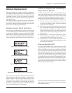
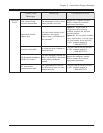
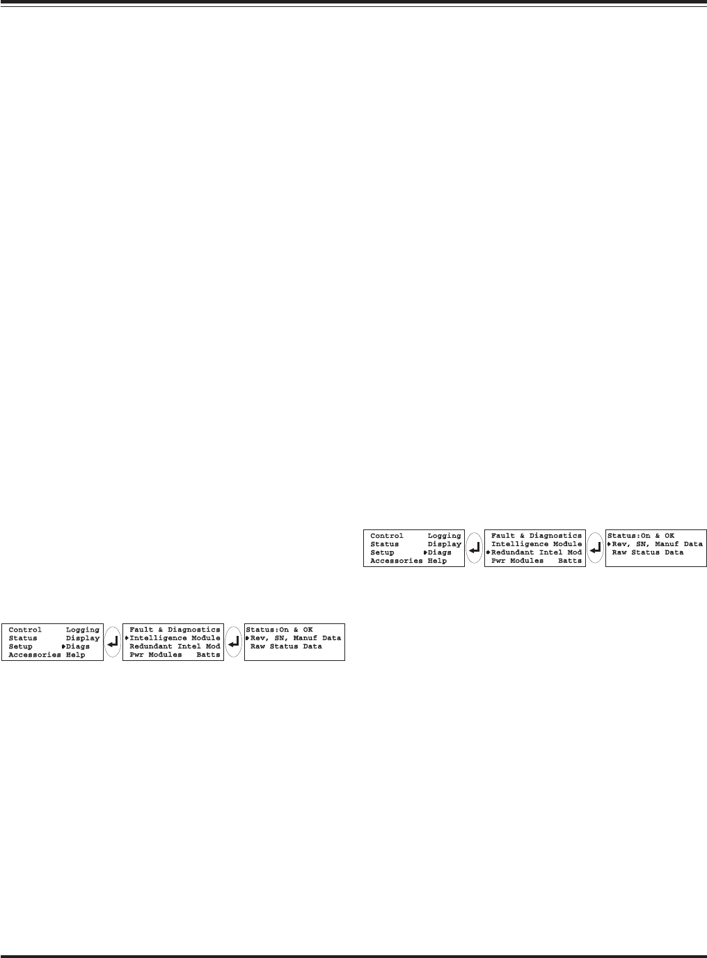
Replacement MIM Verification
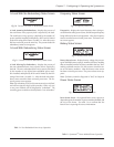
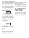
From the startup screen, press any key to open the top level menu
screen. Follow the sequence in figure 8-10 to insure that the
replacement MIM is functioning properly. (Status: On & OK).
Fig 8-10 Intelligence Module Verification
Redundant Intelligence Module
Replacement
The following section provides the procedure for replacing the
redundant intelligence module.
Removing the Redundant Intelligence
Module
1. Remove the grill cover from the top level of the Power Array.
Note: The redundant intelligence module resides above the intelli-
gence module, in the upper right corner of the frame.
2. A RIM can only be replaced if a functioning MIM is installed,
or the load equipment is switched off.
3. Use a flathead screwdriver to release the fliplatch.
4. Unscrew and release the retaining screws.
5. Slide the RIM out of the frame.
Installing the Replacement Redundant
Intelligence Module
Refer to chapter 5 for the RIM installation procedure.
Note: A RIM alone is not adequate to restart the Symmetra
TM
.
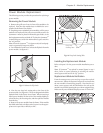
Replacement Redundant Intelligene Module
Verification
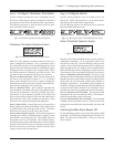
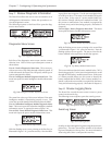
From the startup screen, press any key to open the top level menu
screen. Follow the sequence in figure 8-11 to insure that the
replacement RIM is functioning properly. (Status: On & OK).
Fig 8-11 Redundant Intelligence Module Verification