


Space and Weight Considerations
All Power Array frames are 24” wide and 27” deep. Refer to
table 4-1 for dimensions and weights of fully loaded systems.
Table 2-1 Power Array Dimensions and Weights (Fully
Loaded with Modules)
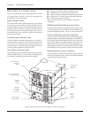
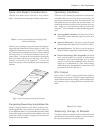
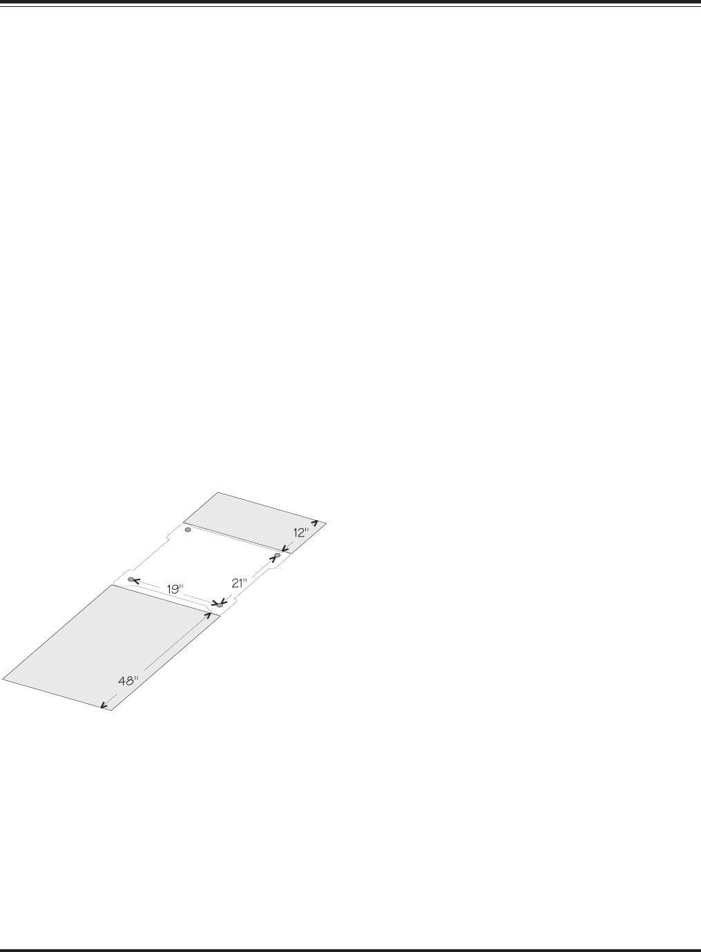
Make sure there is adequate space and structural integrity to
support the fully loaded frame. Refer to figure 2-1 below. The
weight of the Power Array rests on four 1.5” diameter leveling
feet. Positions of the leveling feet are shown. When installing
the frame, allow 12” of clearance behind the frame for ad-
equate airflow. (The fans on the system pull air in through the
front of the frame, and blows it out the back.) Allow 48” of
clearance in the front of the Symmetra
TM
to access the
PowerView interface, and for installation and replacement of
modules.
Fig 2-1 System Footprint and Required Clearance
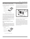
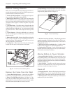
Transporting Power Array to Installation Site
When it is shipped, the Power Array frame is bolted to a cus-
tom-designed pallet. The modules are stacked on either one
or two additional pallets. It is recommended that these pallets
be moved from the receiving dock to the installation area with
a pallet jack. Make sure there is enough space and structural
integrity to move these pallets.
Operating Conditions
The Power Array is intended for installation in a temperature-
controlled, indoor area, free of conductive contaminants. The
operating evironment must be clean, dry and protected. The
atmosphere must be free of dust and corrosive fumes. Ad-
equate airflow must be provided for the operation of the sys-
tem. Make sure environmental conditions where the
Symmetra
TM
is to be installed are within the following param-
eters:
n Operating Relative Humidity: The Power Array will op-
erate within a relative humidity range of 0 to 95%, non-
condensing.
n Operating Temperature: The Power Array will operate
within a temperature range of 32°F to 104°F (0°C to 40°C).
n Operating Elevation: The Power Array will operate at
elevations within a range of 0ft to 10,000ft (0m to 3,048m).
n Electro-Static Discharge (ESD) Susceptibility: The Power
Array and all modules are capable of withstanding
“through air” electro-static discharges up to an ampli-
tude of +/-15kV and “direct discharge” electro-static dis-
charges up to an amplitude of +/-8kV without failure,
abnormal operation or degradation in performance. ESD
test methods conform to IEC 801-2.
BTU Output
Refer to table 2-2 for BTU output of a fully loaded, and func-
tioning Power Array system. The BTU output is significantly
higher while the batteries are charging. Under normal operat-
ing conditions, battery recharge periods are relatively infre-
quent.
Table 2-2 BTU Output
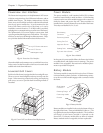
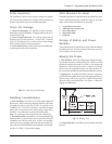
Temporary Storage of Modules
The battery and power modules must be temporarily stored
until the frame is permanently installed. To preserve battery
life, always store batteries in a cool, dry place.
Chapter 2 - Site Preparation
2-1
Rear
Clearance
Footprint and
Feet Positions
Front Clearance