


Chapter 1 Setting Up the CoreModule 800
6 QuickStart Guide CoreModule 800
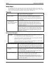
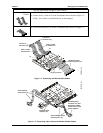
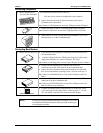
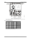
IDE Cable &
Connectors (J6)
(Second IDE
connector not
shown for
simplicity.)
Video Cable &
Connectors (J1)
Ethernet (RJ45)
Adapter Board (J3)
CoreModule 800
Power In
Cable &
Connectors (J7)
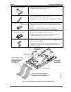
Utility 2 Cable connected
between J5 on I/O Board
and J5 on CoreModule 800
Utility 1 Cable
connected between
J4 on I/O Board
and J4 on
CoreModule 800
Utility 2
Connector (J5)
Utility 1a
Connector (J4)
Utility 2a
Connector (J5)
Utility 1
Connector (J4)
Floppy Disk Drive
(FDD) Cable &
Connectors (J11)
I/O Interface Board
(I/O Board)
CM800QkS_07a
Figure 1-6. Complete CoreModule 800 Cable Assembly
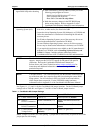
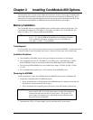
Utility 2a (J5)
Utility 1a (J4)
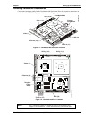
Reset Switch
(SW2)
Power Button
Switch (SW1)
Serial Ports
1 & 2 (J7A/B)
PS/2 Keyboard/Mouse
(J9A/B)
USB Ports
0 & 1 (J8A/B)
Parallel (LPT1)
Port (J12)
Floppy Disk
Drive (FDD)
Interface (J11)
Serial TX/TTL
Jumper (JP1)
SMBus (J10)
I/O Interface Board
(I/O Board)
CM800QkS_06b
Figure 1-7. I/O Interface Board Connections