


Chapter 1 Setting Up the CoreModule 800
4 QuickStart Guide CoreModule 800
Skip any steps that do not apply to your situation.
1) Connect Utility 1 &
2 Cables
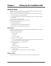
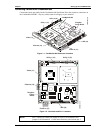
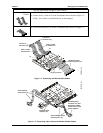
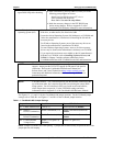
• Connect Utility 1 cable to J4 on the CoreModule 800 as shown in Figure 1-3.
• Connect Utility 2 cable to J5 on the CoreModule 800 as shown in Figure 1-3.
Utility 1 and 2 cables are identical and can be interchanged.
2) Connect IDE cable
• Connect the IDE cable to J6 on the CoreModule 800 as shown in Figure 1-3.
CM800QkS_04a
Connect to
I/O Board (J5)
Connect to
I/O Board (J4)
Utility 2 Cable
& Connectors
Utility 1 Cable
& Connectors
J4
J5
44-pin Connector
IDE Device Cable
and Connectors (J6)
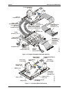
Figure 1-3. Connecting the IDE and Utility Cables
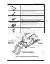
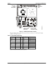
Video Cable &
Connectors (J1)
Power Adapter Cable
& Connectors (J7)
Ethernet RJ45
Adapter (J3)
Standard power
connector for hard
disk drives (HDD)
found on AT or ATX
power supplies.
CM800QkS_05a
Figure 1-4. Connecting Video, Ethernet and Power Cables/Adapter