


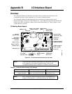

Appendix B I/O Interface Board
CoreModule 800 QuickStart Guide 27
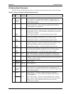
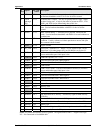
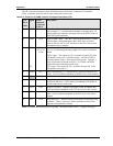
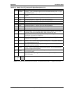
J5
Pin #
Signal OnBoard
Pin #
Description
17 PD7 J12--17 Parallel Data 7 – Refer to PD0, pin 3, for more information.
18 GND GND Ground
19 ACK*
DS1
J12-19
J11-12
Parallel Acknowledge – Status output signal from the printer. A Low
State indicates it data received and is ready to accept new data.
Floppy Drive Select 1 – Selects drive 1.
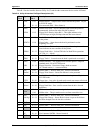
20 GND GND Ground
21 BSY
MTR1*
J12-21
J11-16
Parallel Busy – Status output signal from the printer. A High State
indicates the printer is not ready to accept data.
Floppy Motor Control 1 – Selects motor on drive 1.
22 GND GND Ground
23 PE
WData*
J12-23
J11-22
Parallel Paper End – Status output signal from the printer. A High
State indicates it is out of paper.
Floppy Write Data – Encoded data sent to drive for write operations.
24 GND GND Ground
25 Slct
Wgate*
J12-25
J11-24
Parallel Select – Status output signal from the printer. A High State
indicates it is powered on.
Floppy Write Gate – Enables drive current flow in the write head.
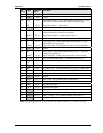
26 IRFIRM J6-5 Infrared Function Mode Select – To external device from J6-5.
27 PM_Sus
Clk
J6-4 Power Management Suspend Clock –
28 GND GND Ground
29 IRTX U2-7 IR Transmit Data – To infrared transceiver TX pin (U2, HSDL-3200)
30 IRRX U2-6 IR Receive Data – To infrared transceiver TX pin (U2, HSDL-3200)
31 SPKR+ LS1-1 Speaker + Drive – To positive terminal on Beep Speaker (LS1)
32 GND GND Ground
33 RstSW SW2-3/4 Reset Switch – Puts ground on this pin when pressed.
34 PwrBtn SW1-3/4 Power On Switch – Puts ground on this pin when pressed.
35 KBDT J9-A1 Keyboard Data signal
36 KBCK J9-A6 Keyboard Clock signal
37 GND GND Digital Ground
38 VCC VCC +5V +/-5%
39 BATV+ BAT1-1 Battery + Voltage – To + terminal on Battery socket (BAT1).
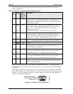
40 GND GND Ground
Notes: The shaded area denotes power or ground. The signals marked with * = Negative true logic.