


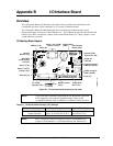


Appendix B I/O Interface Board
CoreModule 800 QuickStart Guide 31
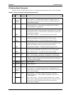
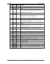
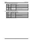
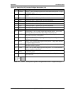
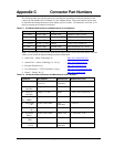
Table B-9. Mouse Interface Pin/Signal Descriptions (J9B)
J9B
Pin #
Signal From Onboard
Connector & Pin #
Description
1 MSDAT J4-31 Mouse Data
2, 4 NC NA Not connected
3 GND J5-37 Ground
5 KBVCC J5-38 Mouse Power (+5V +/-5%) – Provided through shared
Fuse (F1) to mouse voltage pin.
6 MSCLK J4-32 Mouse Clock
Note: The shaded area denotes power or ground.
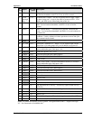
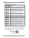
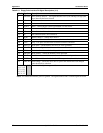
Table B-10. SMBus Interface Pin/Signal Descriptions (J10)
J10
Pin #
Signal From Onboard
Connector & Pin #
Description
1 SMB_Clk J5-22 System Management Bus Clock
2 SMB_Data J5-16 System Management Bus Data
3 SMB_Alert J5-10 System Management Bus Alert
4 VCC J5-38 +5 volts +/-5%
5 GND NA Ground
Note: The shaded area denotes power or ground.