


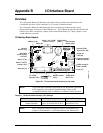


Appendix B I/O Interface Board
30 QuickStart Guide CoreModule 800
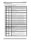
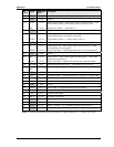
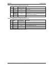
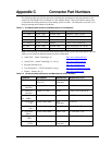
Table B-6. Miscellaneous Interface Pin/Signal Descriptions (J6)
J6
Pin #
Signal From Onboard
Connector & Pin #
Description
1 PS_ON J4-10 Power Supply On – This signal from the I/O hub on
CoreModule 800 can be used to turn on a power supply.
2EXTSMI* J4-36
External SMI – External System Management Interrupt
(SMI) signal from an external source is fed directly to
the I/O Hub.
3BATLOW* J4-38
Battery Low – This signal from an external device or
battery indicates there is insufficient power to system.
4 PM_SUSCLK J5-27 Suspend Clock – This output signal from the I/O Hub
can be used by external devices as a refresh clock.
5 FIRMODE J5-26 IR Mode Select – Terminated with 10k ohm resistor to
ground on CoreModule 800.
Notes: The shaded area denotes power or ground. The signals marked with * = Negative true logic.
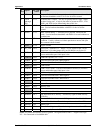
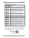
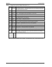
Table B-7. USB Port 0 & 1 Interface Pin/Signal Descriptions (J8)
J8
Pin #
Signal From Onboard
Connector & Pin #
Description
1 USBPWR0 U1-8
+5V (+/-5%) – Power through Power Distribution
Switch (U1) with current limit. Disables this pin if
current exceeds limit.
2 USB0- J4-23 USB Port 0 Data Negative Polarity
3 USB0+ J4-24 USB Port 0 Data Positive Polarity
4 USB GND NA Ground
5 USBPWR1 U1-5 +5V (+/-5%) – Power through Power Distribution
Switch (U1) with current limit. Disables this pin if
current exceeds limit.
6 USB1- J4-28 USB Port 1 Data Negative Polarity
7 USB1+ J4-29 USB Port 1 Data Positive Polarity
8 USB GND NA Ground
9, 10 SHLD GND NA Shield Ground
11, 12 SHLD GND NA Shield Ground
Note: The shaded area denotes power or ground.
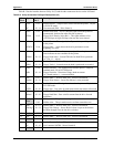
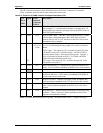
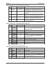
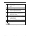
Table B-8. Keyboard Interface Pin/Signal Descriptions (J9A)
J9A
Pin #
Signal From Onboard
Connector & Pin #
Description
1 KBDAT J5-35 Keyboard Data
2, 4 NC NA Not connected
3 GND J5-37 Ground
5 KBVCC J5-38 Keyboard Power (+5V +/-5%) – Through shared Fuse
(F1) to keyboard voltage pin.
6 KBCLK J5-36 Keyboard Clock
Note: The shaded area denotes power or ground.