


CoreModule 800 QuickStart Guide 23
Appendix B I/O Interface Board
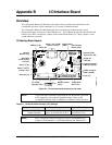
Overview
The I/O Interface Board (I/O Board) provides the I/O device connections and interface to the
CoreModule 800 in the Utility connectors (J4, J5) on the I/O Interface Board.
The I/O Interface Board (I/O Board) provides the I/O connections for the keyboard, mouse,
floppy/parallel port, serial ports (2) and USB ports (2). The I/O Board also provides the Infrared (IR)
transceiver for IrDA connections, a battery socket with Lithium battery, PC "Beep" speaker, a reset
switch and power on switch.
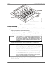
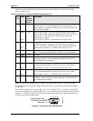
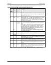
I/O Interface Board Layout
J7
Bat1
SW2 SW1
U2
U4
U1
D1
D2
F1
J9
LS1
J5
J4
J10 J6
JP1
U3
J12
J11
D3
J8
Reset PwrBtn
FDD
Utility 2a (J5)
Utility 1a (J4)
SMBus (J10)
Misc (J6)
Serial 1 & 2 (J7A/B)
(Serial 1 Lower)
Reset Switch
(SW2)
Power Button
Switch (SW1)
PC “Beep”
Speaker (LS1)
Battery Socket
(Bat1)
Power On
LED (D3)
Infrared (IrDA)
Transceiver (U2)
Keyboard (Lower)
& Mouse (J9A/B)
USB 0 (Lower) &
(J8A/B) USB 1
Floppy Disk
Drive (J11)
Fuse (F1)
Hard Disk
Drive Activity
LED (D1)
Thermal
Monitor (U3)
Serial 2 TX/TTL
Jumper (JP1)
CM800QkS_12a
Figure B-1. I/O Interface Board Connectors (Top view)
NOTE If you need more information concerning the I/O Board than is provided
in this Appendix, refer to the I/O Interface Design Library on the
CoreModule 800 Doc & SW CD-ROM for a schematic, BOM, and AVL.
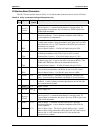
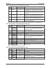
Table B-1. I/O Interface Board Jumper (JP1) Settings
Jumper # Installed Removed/Enabled
JP1 – Serial 2 TX/TTL
Jumper (onboard)
Normal (Default) TX signal
(pins 1-2) to Serial Port 2 (J4-3)
TTL signal (pins 2-3) to
Serial Port 2 (J4-3)
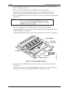
NOTE Pin-1 is shown as a black pin (square or circle) in all connectors and
jumpers in all illustrations. A small diamond may also indicate pin-1.