


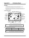


Appendix B I/O Interface Board
34 QuickStart Guide CoreModule 800
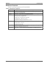
Miscellaneous Components
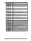
Table B-13 list the helpful components on the I/O Interface Board.
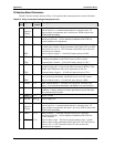
Table B-13. Miscellaneous Components
Component Description
Battery Battery Socket (BAT1) – Supports external Lithium (3.0V) battery for the Real
Time Clock on CoreModule 800.
Fuse (F1) Auto-reset, 1.5 Amp shared fuse for keyboard and mouse.
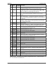
LED (D1) Green Hard Disk Drive Activity LED (D1) – Indicates activity on the IDE connector
(J6) located on the CoreModule 800.
• Steady Green = No IDE devices connected.
• Flashing Green = IDE device activity
• Steady Off = IDE device connected, but no activity.
LED (D3) Yellow Power On LED (D3) – Indicates power state of the CoreModule 800.
• Steady Yellow = Power On
• Steady Off = Power Off
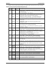
Switch (SW1) Power Button Switch – Provides external Power on signal (ground) through the
interface to CoreModule 800 on pin J5-34.
Switch (SW2)
Reset Switch – Provides external reset signal (ground) to CoreModule 800 on pin
J5-33.