


Chapter 1 Setting Up the CoreModule 800
10 QuickStart Guide CoreModule 800
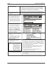
f) For LAN Boot, go to PXE Boot
Agent BIOS Setup after rebooting
• Enter PXE BIOS by pressing Ctrl + S, when you see the
following prompt appear on screen:
Initializing Intel (R) Boot Agent FE v4.x.xx
PXE v2.0 Build 084 (WfM 2.0)
Press Ctrl + S to enter the setup Menu..
• Make the necessary changes in the PXE BIOS Setup
before saving changes. Refer to Appendix C of the
CoreModule 800 Reference Manual for more information.
20) Install the desired
Operating System (OS)
• Use the LAN Boot feature to load the boot (OS) image onto the hard
disk drive, or other media. (See Note below) Or
• Locate the desired Operating System (OS) diskette(s) or CD-ROM and
follow the manufacturer’s instructions for installing the OS and the
necessary drivers.
For Windows Operating Systems, most of the necessary drivers are
found on the manufacturer’s installation CD-ROM.
For non-Windows Operating Systems, some or all of the necessary
drivers may be found on the manufacturer’s diskette(s) or CD-ROM.
• If you require drivers that are not available on the OS manufacturer’s
diskette(s) or CD-ROM, refer to Installing Software, Drivers, and
Utilities in Chapter 2 and the software subdirectory on the
CoreModule 800 Doc & SW CD-ROM for the files and instructions.
NOTE The CoreModule 800 ships from the factory configured only for CRT
support. Ampro provides LCD/TFT support for flat panels with specific
resolutions. Refer to the CoreModule 800 Reference Manual, the
Release Notes, and Virtual Technician at http://ampro.custhelp.com for
instructions and additional information when customizing the BIOS to a
particular flat panel.
NOTE LAN Boot Feature – The LAN Boot process puts the Ethernet connection at the
top of the boot order, but it requires more than just selecting the correct BIOS
Setup options. You will also need a PXE server with its tools and utilities,
which Ampro does not provide. For the PXE BIOS settings and more
information refer to Appendix C of the CoreModule 800 Reference Manual.
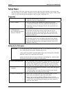
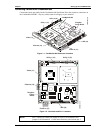
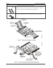
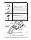
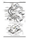
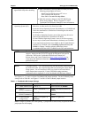
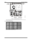
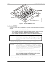
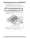
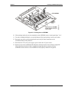
See Figures 1-1, 1-2, and 1-8 for the CoreModule 800 jumper locations. For the I/O Board jumper
settings refer to Table B-1 and Figures 1-7 and B-1 for the I/O Board jumper location.
Table 1-1. CoreModule 800 Jumper Settings
Jumper # Installed Removed/Enabled
JP1 – CMOS Normal/Clear Clear (1-2) Normal (Removed) Default
JP2 – Serial 2
RS-485 Termination
Enable Termination (1-2) Disable Termination (Removed)
Default
JP3 – Serial 1
RS-485 Termination
Enable Termination (1-2) Disable Termination (Removed)
Default
JP4 – LVDS Flat Panel
Voltage Select
Enable +3.3V (pins 1-2)
(Default)
Enable +5V (pins 2-3)
Notes: Jumpers (or shunts) use 2 mm spacing. A jumper that is removed may be placed on one of the
jumper pins for safe keeping.