


Chapter 1 Setting Up the CoreModule 800
CoreModule 800 QuickStart Guide 5
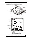
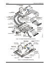
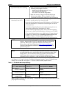
3) Connect the Video Cable
Pin-1
• Connect the Video cable to the Video connector (J1) on the
CoreModule 800 as shown in Figure 1-4.
4) Connect Power Adapter Cable
• Connect the Power Adapter Cable to the Power In connector (J7)
on the CoreModule 800 as shown in Figure 1-4.
See Table 1-2 for Power Adapter Cable wiring and pin connections.
5) Connect the Ethernet
Adapter board
• Connect the Ethernet adapter board provided in the QuickStart Kit
to the Ethernet connector (J3) on the CoreModule 800 as shown in
Figure 1-4.
Refer to the CoreModule 800 I/O Interface Design Library on the
CoreModule 800 Doc & SW CD-ROM for more information.
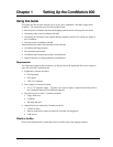
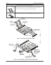
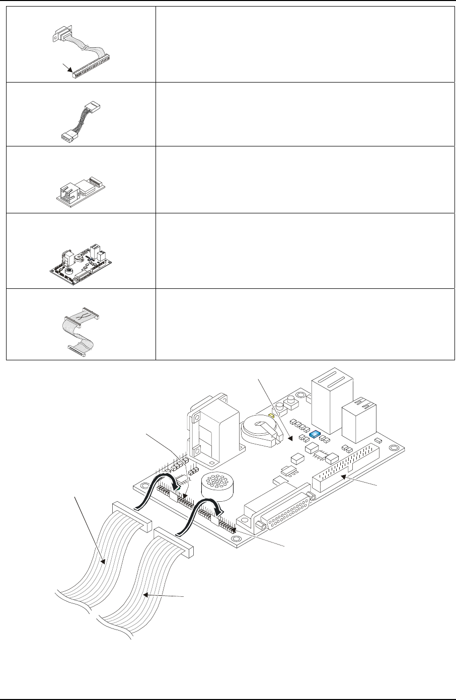
6) Connect Utility Cables
1 & 2 to the I/O Board
• Connect free end of Utility 1 Cable on the CoreModule 800 to J4
on the I/O Board as shown in Figures 1-5 and 1-6.
• Connect free end of Utility 2 Cable on the CoreModule 800 to J5
on the I/O Board as shown in Figures 1-5 and 1-6.
7) Connect Floppy Drive Cable
• Connect a standard 34-pin Floppy drive cable to the Floppy drive
port (J11) on the I/O Board.
The floppy drive interface (J11) is shared with the Parallel (LPT1)
interface (J12), so you can only use one of these connectors at a
time on the I/O Board.
CM800QkS_06a
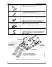
Connect Utility 2 cable between
J5 ( ) on CoreModule 800 and
J5 ( ) on the I/O Board.
Utility 2
Utility 2a
Connect Utility 1 cable
between J4 ( ) on
CoreModule 800 and
J4 ( ) on
the I/O Board.
Utility 1
Utility 1a
Utility 2a (J5)
Utility 1a (J4)
Floppy Disk
Drive (FDD)
Interface (J11)
I/O Interface Board
(I/O Board)
Figure 1-5. Connecting Utility Cables to the I/O Interface Board