


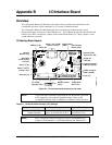


Appendix B I/O Interface Board
CoreModule 800 QuickStart Guide 29
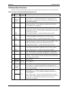
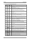
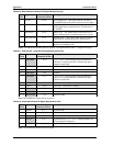
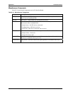
Table B-5 lists the connections on the I/O Board between Serial Port 2 connector (J7A) and the
Utility 1a interface connector (J4) or other connections on the board.
Table B-5. Serial Port 2 (COM2) Interface Pin/Signal Descriptions (J7A)
J7A
Pin #
(DB9)
Signal From
Onboard
Connector
& Pin #
Description
1 DCD2* J4-11 Data Carrier Detect 2 – Indicates external serial device is detecting a
carrier signal (i.e., a communication channel is currently open). In
direct connect environments, this input is driven by DTR2 as part of
the DTR2/DSR2 handshake.
2 RXD2 J4-13 Receive Data 2 Input – This line is typically held at a logic 1 (mark)
when no data is being transmitted, and is held “Off” for a brief
interval after an “On” to “Off” transition on the RTS2 line to allow
the transmission to complete.
3TXD2
TTL
JP1-2
(J4-15, or
J4-20)
Serial Transmit Data 2 Output – The signal on this line comes from
J4-15 or J4-20 thorough the only jumper (JP1) on the I/O Interface
Board.
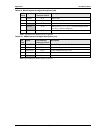
TXD2 signal – This signal (J4-15) is available if jumper JP1 on the
I/O Board is set to pins 1-2 (default setting). This line (TXD2) is
typically held to a logic 1 when no data is being sent. Typically, a
logic 0 (On) must be present on RTS1, CTS1, DSR1, and DTR1
before data can be transmitted on this line.
TTL signal – This signal (J4-20) is available if jumper JP1 on the
I/O Board is set to pins 2-3.
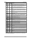
4 DTR2* J4-17 Data Terminal Ready 2 – Indicates port is powered, initialized, and
ready. Used as hardware handshake with DSR2 for overall readiness.
5 GND J4-19 Ground
6 DSR2* J4-12 Data Set Ready 2 – Indicates external serial device is powered,
initialized, and ready. Used as hardware handshake with DTR2 for
overall readiness to communicate.
7RTS2*J4-14
Request To Send 2 – Indicates serial port is ready to transmit data.
Used as hardware handshake with CTS2 for low level flow control.
8 CTS2* J4-16 Clear To Send 2 – Indicates external serial device is ready to receive
data. Used as hardware handshake with RTS2 for low level flow
control.
9 RI2* J4-18 Ring Indicator 2 – Indicates external serial device is detecting a ring
condition. Used by software to initiate operations to answer and
open the communications channel.
Notes: The shaded area denotes power or ground. The signals marked with * = Negative true logic.