


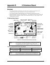


Appendix B I/O Interface Board
CoreModule 800 QuickStart Guide 33
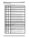
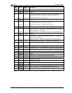
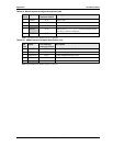
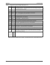
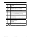
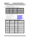
Table B-12. Parallel Port (LPT) Interface Pin/Signal Descriptions (J12)
Pin # Signal Description
1Strobe*
Strobe* – This is an output signal used to strobe data into the printer. I/O pin
in ECP/EPP mode.
2 PD0 Parallel Port Data 0 – These signals <0 to 7> provide the parallel port data
signals
3 PD1 Parallel Port Data 1 – Refer to pin-2 for more information.
4 PD2 Parallel Port Data 2 – Refer to pin-2 for more information.
5 PD3 Parallel Port Data 3 – Refer to pin-2 for more information.
6
PD4 Parallel Port Data 4 – Refer to pin-2 for more information.
7 PD5 Parallel Port Data 5 – Refer to pin-2 for more information.
8 PD6 Parallel Port Data 6 – Refer to pin-2 for more information.
9 PD7 Parallel Port Data 7 – Refer to pin-2 for more information.
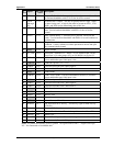
10 ACK* Acknowledge – This is a status output signal from the printer. A Low State
indicates it has received the data and is ready to accept new data.
11 BUSY Busy – This is a Status output signal from the printer. A High State indicates
the printer is not ready to accept data.
12 PE
Paper End – This is a status output signal from the printer. A High State
indicates it is out of paper.
13 SLCT Select – This is a status output signal from the printer. A High State indicates
it is selected and powered on.
14 ALF* Auto Feed – This is a request signal into the printer to automatically feed one
line after each line is printed.
15 ERR* Error – This is a status output signal from the printer. A Low State indicates
an error condition on the printer.
16 INIT*
Initialize – This signal used to Initialize printer. Output in standard mode, I/O
in ECP/EPP mode.
17 SLCTIN* Select In – This output signal is used to select the printer. I/O pin in
ECP/EPP mode.
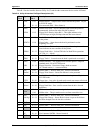
18, 19, 20,
21, 22, 23,
24, 35
GND Ground
Notes: The shaded area denotes power or ground. The signals marked with * = Negative true logic.