


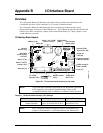


Appendix B I/O Interface Board
32 QuickStart Guide CoreModule 800
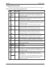
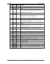
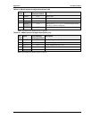
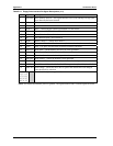
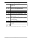
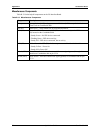
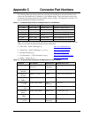
Table B-11. Floppy Drive Interface Pin/Signal Descriptions (J11)
Pin # Signal Description
2DRVEN0
Drive Density Select 0 – This signal indicates a low (250/300 kbps) or high (500
kbps) data rate has been selected.
4 NC Not connected
6 NC Not connected
8 INDEX Index – Detects the drive head is positioned over the track 0.
10 NC Not connected (MTR0 - Motor Control 0)
12 DS1 Drive Select 1 – Selects drive 1.
14 NC Not connected (DS0 - Drive Select 0)
16 MTR1 Motor Control 1 – Selects drive motor 1.
18 DIR Direction – Direction of head movement (0 = inward motion, 1 = outward motion)
.
20 STEP Step – Low pulse for each track-to-track movement of the head.
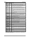
22 WDATA Write Data – Encoded data to the drive for write operations.
24 WGATE Write Gate – Signal to the drive to enable current flow in the write head.
26 TRK0 Track 0 – Sense detects the head is positioned over track 0.
28 WRTPRT Write Protect – Senses the diskette is write protected.
30 RDATA Read Data – Raw serial bit stream from the drive for read operations.
32 HDSEL Head Select – Selects the side for Read/Write operations (0 = side 1, 1 = side 0)
34 DSKCHG Disk Change – Senses the drive door is open or the diskette has been changed
since the last drive selection.
1, 3, 5, 7, 9,
11, 13, 15,
17, 19, 21,
23, 25, 27,
29, 31, 33
GND Ground (All odd pins are grounded)
Notes: The shaded area denotes power or ground. The signals marked with * indicate signal inversion.