


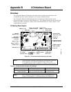

Appendix B I/O Interface Board
26 QuickStart Guide CoreModule 800
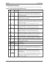
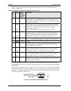
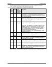
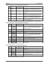
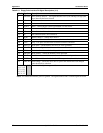
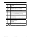
Table B-3 lists the interface between Utility 2a (J5) and the other connectors/devices on the I/O Board.
Table B-3. Utility 2a Interface Pin/Signal Descriptions (J5)
J5
Pin #
Signal
OnBoard
Pin #
Description
1STB*
NC
J12-1
J11-14
Parallel Strobe* – Output used to strobe data into the printer. I/O pin
in ECP/EPP mode.
Not connected (DS0 – Drive Select 0)
2AFD*
DEN0
J12-2
J11-2
Parallel Auto Feed – This is a Request signal sent to the printer to
automatically feed one line after each line is printed.
Floppy Drive Density Select Bit 0 – This signal indicates a low
(250/300 kbps) or high (500 kbps) data rate has been selected.
3PD0
INDEX*
J12-3
J11-8
Parallel Data 0 – These signals (0 to 7) provide the parallel port data
to the printer.
Floppy Index – Sense detects the head is positioned over the
beginning of a track
4 ERR*
HDSel*
J12-4
J11-32
Parallel Error – This is a Status output signal from the printer. A Low
State indicates an error condition on the printer.
Floppy Head Select – Selects FDD side for Read/Write operations
(0 = side 1, 1 = side 0)
5PD1
TRK0
J12-5
J11-26
Parallel Data 1 – Refer to PD0, pin 3, for more information.
Floppy Track 0 – Sensor detects the head is positioned over track 0.
6PInit*
DIR*
J12-6
J11-18
Parallel Initialize – This signal used to Initialize printer. Output in
standard mode, I/O in ECP/EPP mode.
Floppy Direction – Direction of floppy head movement
(0 = inward motion, 1 = outward motion).
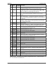
7PD2
WrtPrt*
J12-7
J11-28
Parallel Data 2 – Refer to PD0, pin 3, for more information.
Floppy Write Protect – Senses the diskette is write protected.
8SLIn*
STEP*
J12-8
J11-20
Parallel Select In – This signal used to select the printer. I/O pin in
ECP/EPP mode.
Floppy Step – Low pulse for each track-to-track movement of the head.
9PD3
RData*
J12-9
J11-30
Parallel Data 3 – Refer to PD0, pin 3, for more information.
Floppy Read Data – Raw serial bit stream from the drive for read
operations.
10
SMB_
Alert
U3-11
J10-3
SMBus Alert – This pin receives signals from thermal monitor (U3).
SMBus Alert – This pin sends/receives to/from external devices.
11 PD4
DskChg*
J12-11
J11-34
Parallel Data 4 – Refer to PD0, pin 3, for more information.
Floppy Disk Change – Senses the drive door is open or the diskette
has been changed since the last drive selection.
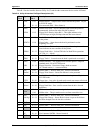
12 GND GND Ground
13 PD5 J12-13 Parallel Data 5 – Refer to PD0, pin 3, for more information.
14 GND GND Ground
15 PD6
NC
J12-15
J11-10
Parallel Data 6 – Refer to PD0, pin 3, for more information.
Not Connected (MTR0 – Motor Control 0)
16 GND GND Ground