


OCTO² / QFX402 Chapter 2 : STARTING (continued)
PAGE 15
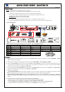
2-3. INPUT #1 DESCRIPTION
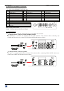
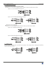
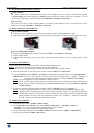
c CONNECTION:
You can connect to this input one of the following source:
• A composite video source.
• A S.VIDEO source.
• A Component video source (YUV).
• A HD-YUV source.
• A RGBS video source.
• An analog (RGBHV, RGsB, RGBS) computer source.
NOTE:
You can use the DVI / HD15 adaptor provided with the device to connect analog sources on the DVI-I (IN)
connector.
• A digital computer source.
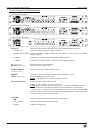
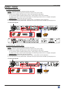
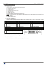
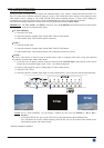
d DVI-I PIN ASSIGNMENT:
The DVI-I female connector of the device can be used with digital signals as well as analog signals. The table
hereafter explain the pin assignment of this connectors.
Pin
Function
Pin
Function
Pin
Function
1
TMDS Data 2-
9
TMDS Data 1-
17
TMDS Data 0-
2
TMDS Data 2+
10
TMDS Data 1+
18
TMDS Data 0+
3
TMDS Data 2 Shield
11
TMDS Data 1 Shield
19
TMDS Data 0 Shield
4
Not used.
12
Not used.
20
Not used.
5
Not used.
13
Not used.
21
Not used.
6
DDC Clock
14
+ 5V (Power)
22
TMDS Clock Shield
7
DDC Data
15
Ground for (+5V)
23
TMDS Clock+
8
Analog Vertical Sync.
16
Hot plug detect.
24
TMDS Clock-
C1
Analog Red video (or Cr / Pr or C)
C2
Analog Green Video (or Y or composite video)
C3
Analog Bleu Video (or Cb / Pb)
C4
Analog Horizontal Sync (or composite sync)
C5
Analog Common Ground Return
DDC = Display Data Channel.
TMDS = Transition Minimized Differential Signal.
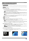
e AUDIO SOURCE:
You can also connect an AUDIO stereo source on jack 3.5 connectors.
8
1
9
16
24
17
C1 C2
C3
C4
C5