


Chapter 2 : STARTING (continued) OCTO² / QFX402
PAGE 16
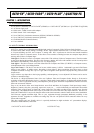
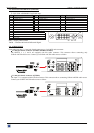
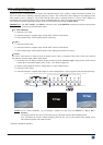
2-4. INPUTS #2 to 8 DESCRIPTION
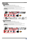
c CONNECTION:
You can connect to these inputs one of the following source:
• A composite video source.
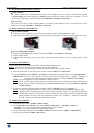
NOTE
: The input #7 can accept a composite video source on its BNC connector. The input #8 can accept a
composite video source on its RCA connector.
• A S.VIDEO source.
NOTE
: The input #7 can accept a S.VIDEO source on its BNC connectors. The input #8 can accept a S.VIDEO
source on its 4-pin mini DIN connector.
• A Component video source.
• A HD-YUV source.
• A RGBS video source.
• An analog computer source (RGBHV, RGsB, RGBS).
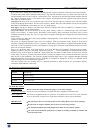
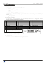
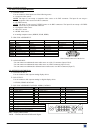
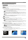
d HD15 PIN ASSIGNMENT:
SIGNAL COMPUTER (analog) VIDEO RGB/S YUV & HD-YUV S.VIDEO (Y/C) COMPOSITE VIDEO
PIN 1 RED. RED. Cr / Pr. C (chrominance).
PIN 2 GREEN. GREEN. Y. Y (luminance). VIDEO (NTSC, PAL...)
PIN 3 BLUE. BLUE. Cb / Pb.
PIN 6 RED return. RED return. Cr / Pr return. C return.
PIN 7 GREEN return. GREEN return. Y return. Y return. return.
PIN 8 BLUE return. BLUE return. Cb / Pb return.
PIN 10 GND. GND.
PIN 13 H sync or C sync (S). C sync (S).
PIN 14 V sync.
HD15 female connector of the device.
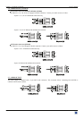
e AUDIO SOURCE:
-You can connect an unbalanced stereo audio source on a jack 3.5 connector (input #2 & 8).
-You can connect an unbalanced stereo audio source on a MCO connector (input #3 to 6).
-You can connect an unbalanced or balanced stereo audio source on a MCO connector (input #7).
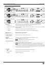
2-5. OUTPUTS DESCRIPTION
c ANALOG OUTPUT:
You can connect to this output an analog display device.
d DVI OUTPUT:
You can connect to this output an analog* or digital display device.
* OFX803, OFD803 & OCP803.
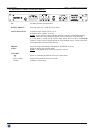
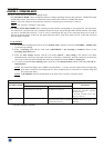
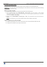
e DVI-I PIN ASSIGNMENT (OFX803, OFD803, OCP803):
Pin
Function
Pin
Function
Pin
Function
1
TMDS Data 2-
9
TMDS Data 1-
17
TMDS Data 0-
2
TMDS Data 2+
10
TMDS Data 1+
18
TMDS Data 0+
3
TMDS Data 2 Shield
11
TMDS Data 1 Shield
19
TMDS Data 0 Shield
4
Not used.
12
Not used.
20
Not used.
5
Not used.
13
Not used.
21
Not used.
6
DDC Clock
14
+ 5V (Power)
22
TMDS Clock Shield
7
DDC Data
15
Ground for (+5V)
23
TMDS Clock+
8
Analog Vertical Sync.
16
Hot plug detect.
24
TMDS Clock-
C1
Analog Red video (or Cr / Pr or C)
C2
Analog Green Video (or Y or composite video)
C3
Analog Bleu Video (or Cb / Pb)
C4
Analog Horizontal Sync (or composite sync)
C5
Analog Common Ground Return
DDC = Display Data Channel.
TMDS = Transition Minimized Differential Signal.
5
6
1
15
10
11
8
1
9
16
24
17
C1 C2
C3
C4
C5