


OCTO² / QFX402 Chapter 2 : STARTING (continued)
PAGE 17
2-5. OUTPUTS DESCRIPTION (continued)
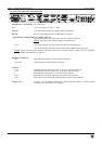
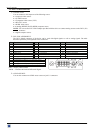
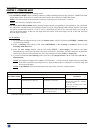
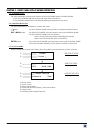
f DVI-I PIN ASSIGNMENT (QFX402 only):
Pin
Function
Pin
Function
Pin
Function
1
TMDS Data 2-
9
TMDS Data 1-
17
TMDS Data 0-
2
TMDS Data 2+
10
TMDS Data 1+
18
TMDS Data 0+
3
TMDS Data 2 Shield
11
TMDS Data 1 Shield
19
TMDS Data 0 Shield
4
Not used.
12
Not used.
20
Not used.
5
Not used.
13
Not used.
21
Not used.
6
DDC Clock
14
+ 5V (Power)
22
TMDS Clock Shield
7
DDC Data
15
Ground for (+5V)
23
TMDS Clock+
8
Analog Vertical Sync.
16
Hot plug detect.
24
TMDS Clock-
C1
Not used
C2
Not used
C3
Not used
C4
Not used
C5
Not used
DDC = Display Data Channel.
TMDS = Transition Minimized Differential Signal.
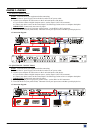
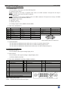
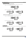
2-6. AUDIO INPUTS
Each audio input has a 3.5 mm jack female connector or a 5-pin MCO male connector.
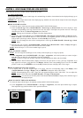
• 3.5 mm jack female connector (OFX803, OFD803, OCP803)
The INPUTS # 1, 2, and 8 are equipped with this audio connector. This connector allows connecting only
UNBALANCED audio source. Connect your UNBALANCED audio sources as follow:
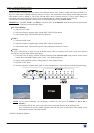
• 3.5 mm jack female connector (QFX402)
The input # 1 is equipped with this audio connector. This connector allows connecting UNBALANCED audio source.
Connect your UNBALANCED audio sources as follow:
8
1
9
16
24
17
C1 C2
C3
C4
C5