11
Installing the Support Brackets
1. Verify the contents of the kit. It contains: two adjustable-length L-channel supports, eight clip
nuts, eight 10-32 x 1/2” flat-head screws, and eight washers. The washers are for use with
square rack holes only.
2. If the rack uses threaded holes, drill out the appropriate front rail rack holes with a 7/32” drill
bit. This step is not required when mounting in racks with square holes.
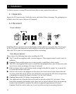
3. Install clip nuts on the uppermost and lowermost holes at each end of the L-channel sup-
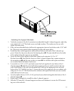
ports. Orient the clip nut as shown in the drawing above ➌. The nuts should be to the inside
of the cabinet when the supports are installed.
4. Secure the front of the support to the front cabinet rack using two 10-32 x 1/2”
flat-head screws ➍. Note that the front ear of the L-channel support has a square cutout on
the mounting ear ➊, and the rear ear has no cutout ➋. For cabinets with square rack holes,
use a washer under the head of each screw.
5. Loosen the two 10-32 x 5/16” pan-head screws that lock together the two halves of the L-
channel support ➎. Slide the outer half of the support to the rear until it contacts the rear
rack of the cabinet. If the rack uses threaded holes, drill out the appropriate rear rail rack
holes with a 7/32” drill bit (see Step 3). Secure the rear of the support to the rear cabinet rack
using two 10-32 x 1/2” flat-head screws.For cabinets with square rack holes, use use a washer
under the head of each screw.
6. Securely tighten the two 10-32 x 5/16” pan-head screws that lock together the halves of the L-
channel support ➎.
7. Repeat steps 3 through 6 to install the other L-channel support.
8. Slide the UPS onto the L-channel supports and use rack hardware to secure the UPS mount-
ing ears to the rack rails.


