


13
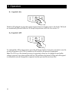
4.4 Install Accessory (Optional)
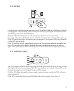
Some UPS accessories connect to the computer interface (DB-9) port, while others install in the
accessory slot. See the literature accompanying the accessory to determine proper installation. The
screws holding the slot cover are #2 Phillips head type.
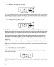
To use the computer interface port, connect the accessory to the DB-9 connector and tighten
down the connector’s screws.
Connect the optional battery pack (3000 VA model only) according to the instructions with the
battery pack.
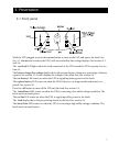
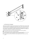
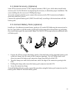
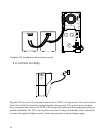
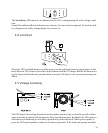
4.5 Connect Battery Packs (optional)
Install up to 10 additional external battery packs per XL model UPS following the instructions be-
low. See your dealer or call the number at the front of this manual for information on purchasing
the correct battery pack for your model. Note: The 3000 VA UPS accepts only one additional exter-
nal battery pack.
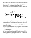
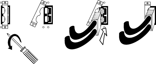
1. Prepare the UPS to connect the battery pack(s). Note the holes used to attach the battery pack
connector clamp (near the center of the connector opening). Use a #2 Phillips head screw-
driver to remove the battery pack connector clamp from the back of the UPS.
2. Turn the clamp over and loosely attach one end at the edge of the connector opening in the
UPS.
3. Holding the clamp aside, insert the battery pack connector into the UPS.
4. Secure the connector clamp.
To install additional battery packs, repeat this procedure using the battery pack connectors on the
battery packs. Note: Do not stack battery packs.