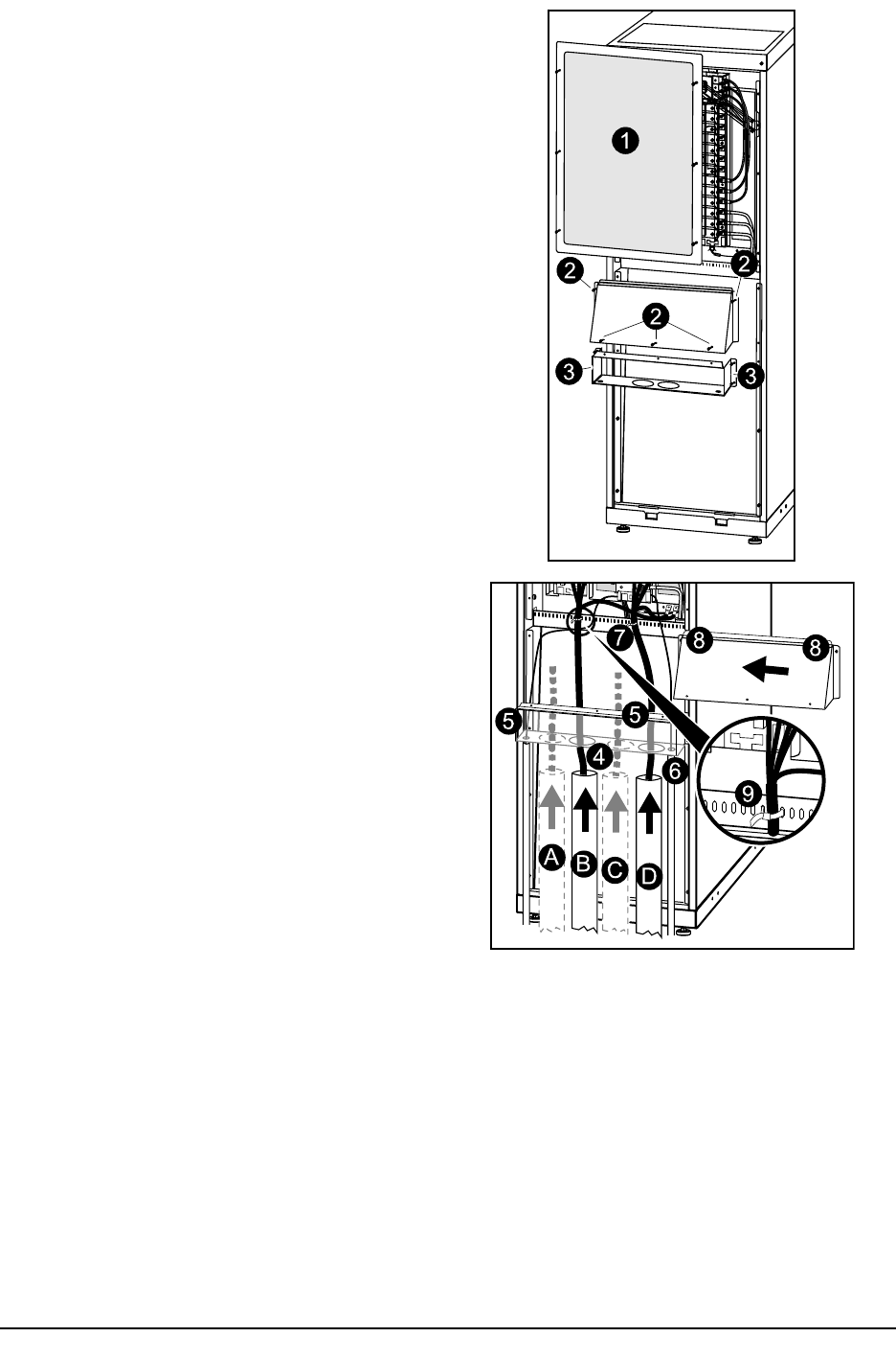
Prepare for Cables
Bottom Cable Entry
1. From the rear of the UPS, loosen the six M4
screws from the upper cover (the cable landing
area), and remove. Save the screws for later
use
2. Loosen the two M4 screws (one on each side)
from the top part of the conduit box. Loosen
the M4 screws attaching it to the bottom part
(two screws in 352 mm (13.8 in) enclosure
three screws in a 523 mm (20 in) enclosure)
and remove. Save the screws for later use.
3. Loosen the four M4 screws (two on each side)
from the conduit box and remove. Save the
screws for later use.
4. Punch as many holes as needed in the marked
areas of the bottom conduit box.
5. Attach the conduit box bottom to the enclosure
(reuse the screws from step 3).
6. Attach conduits to the conduit box.
7. Run the cables through the conduits, the
bottom of the conduit box, and up into the
cable landing area.
A.Bypass
B. Output
C. Battery
D.Input
8. Attach conduit box top to the conduit box
bottom and to the enclosure reusing the screws
from step 2.
9. Fasten the cables with cable ties.
A
B
C
D
5
5
6
4
7
9
8
8
990-1957C-001
MGE™ Galaxy™ 3500 10-30 kVA 208/220 V Single and Parallel Installation
27


