


22 ASUS K7M User’s Manual
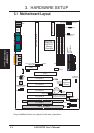
3. HARDWARE SETUP
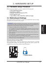
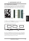
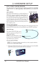
3.5 System Memory (DIMM)
NOTE: No hardware or BIOS setup is required after adding or removing memory.
This motherboard uses only Dual Inline Memory Modules (DIMMs). Sockets are
available for 3.3Volt (power level) unbuffered Synchronous Dynamic Random Ac-
cess Memory (SDRAM) of 16, 32, 64, 128MB, or 256MB. to form a memory size
between 16MB and 768MB. One side (with memory chips) of the DIMM takes up
one row on the motherboard.
To use the chipset’s Error Checking and Correction (ECC) feature, you must use a
DIMM with 9 chips per side (standard 8 chips/side + 1 ECC chip).
Memory speed setup is recommended through Configure SDRAM Timing by SPD
(see 4.4.2 Advanced Chipset Setup).
Install memory in any combination as follows:
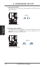
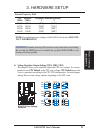
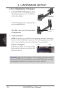
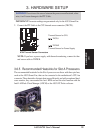
IMPORTANT: DIMMs must be inserted in the following sequence: DIMM1,
DIMM2, DIMM3. That is, if you intend to initially use one DIMM, use DIMM1
first. Then when you are ready for a second DIMM, use DIMM2, and so on. If
this sequence is not followed, system instability may be experienced.
Location 168-pin DIMM Total Memory
DIMM1 (Rows 0&1) SDRAM 16, 32, 64, 128, 256MB x1
DIMM2 (Rows 2&3) SDRAM 16, 32, 64, 128, 256MB x1
DIMM3 (Rows 4&5) SDRAM 16, 32, 64, 128, 256MB x1
Total System Memory (Max 768MB) =
NOTE: At the time this User’s Manual was written, 256MB DIMM’s are only
available as Double-Sided registered memory (128Mbit cells).
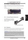
3.5.1 General DIMM Notes
• When this motherboard operates at 100MHz, PC100-compliant modules must
be used because of the strict timing issues involved under this speed.
• This motherboard supports SPD (Serial Presence Detect) DIMMs. This is the
memory of choice for best performance vs. stability.
• SDRAM chips are generally thinner with higher pin density than EDO (Ex-
tended Data Output) chips.
• BIOS shows SDRAM memory on bootup screen.
• Single-sided DIMMs come in 16, 32, 64,128MB; double-sided come in 32, 64,
128, 256MB.
System Memory
3. H/W SETUP