


ASUS K7M User’s Manual 43
3. HARDWARE SETUP
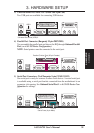
Connectors
3. H/W SETUP
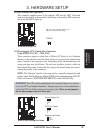
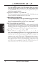
The following PANEL illustration is used for items 21-25 (next page).
010101
K7M
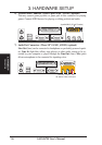
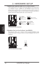
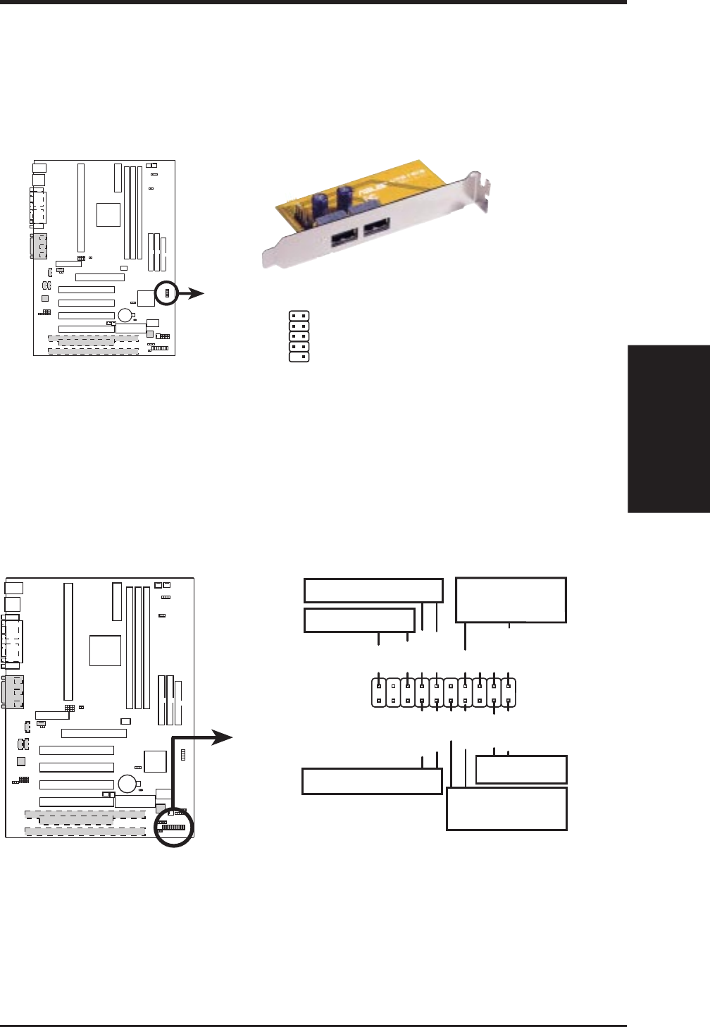
K7M System Panel Connectors
* Requires an ATX power supply.
PLED
Ground
PWR
+5 V
Keylock
+5V
Speaker
Speaker
Connector
Power LED
Ground
Reset SW
SMI Lead
ExtSMI#
+3VSB
Reset
Ground
Ground
Ground
Keyboard Lock
ATX Power
Switch*
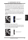
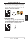
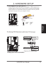
20) USB Connector Set (10-1 pin USBPORT)
If the USB Ports on the back panels are inadequate, a USB connector set is
available midboard. If you want to use this connector, you need to use the bundled
external connector set. The external connector set connects to the 10-1 pin block
and mounts to an open slot on your computer’s chassis.
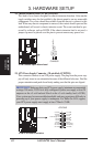
K7M USB Ports 2 and 3
USBPORT
010101
K7M
1: USB Power
2: USBP2–
3: USBP2+
4: GND
5: NC
6: USB Power
7: USBP3–
8: USBP3+
9: GND
Optional USB
1
5
6
10