


42 ASUS K7M User’s Manual
3. HARDWARE SETUP
Connectors
3. H/W SETUP
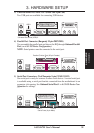
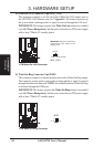
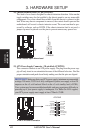
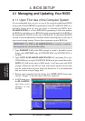
18) Chassis Intrusion Lead (4-1 pin CHASSIS)
This lead is for a chassis designed for chassis intrusion detection. After-market
toggle switches may also be installed to the chassis panel or on any removable
components. Two wires should be available from the chassis to connect to this
lead. When any chassis component is removed, the contact should open and the
motherboard will record a chassis intrusion event. The event can then be pro-
cessed by software, such as LDCM. If the chassis intrusion lead is not used, a
jumper cap must be placed over the pins to prevent unnecessary power loss.
010101
K7M
K7M Chassis Open Alarm Lead
+5Volt
(Power Supply Stand By)
Ground
Chassis Signal
CHASSIS
1
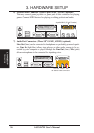
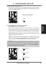
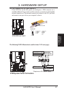
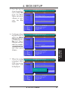
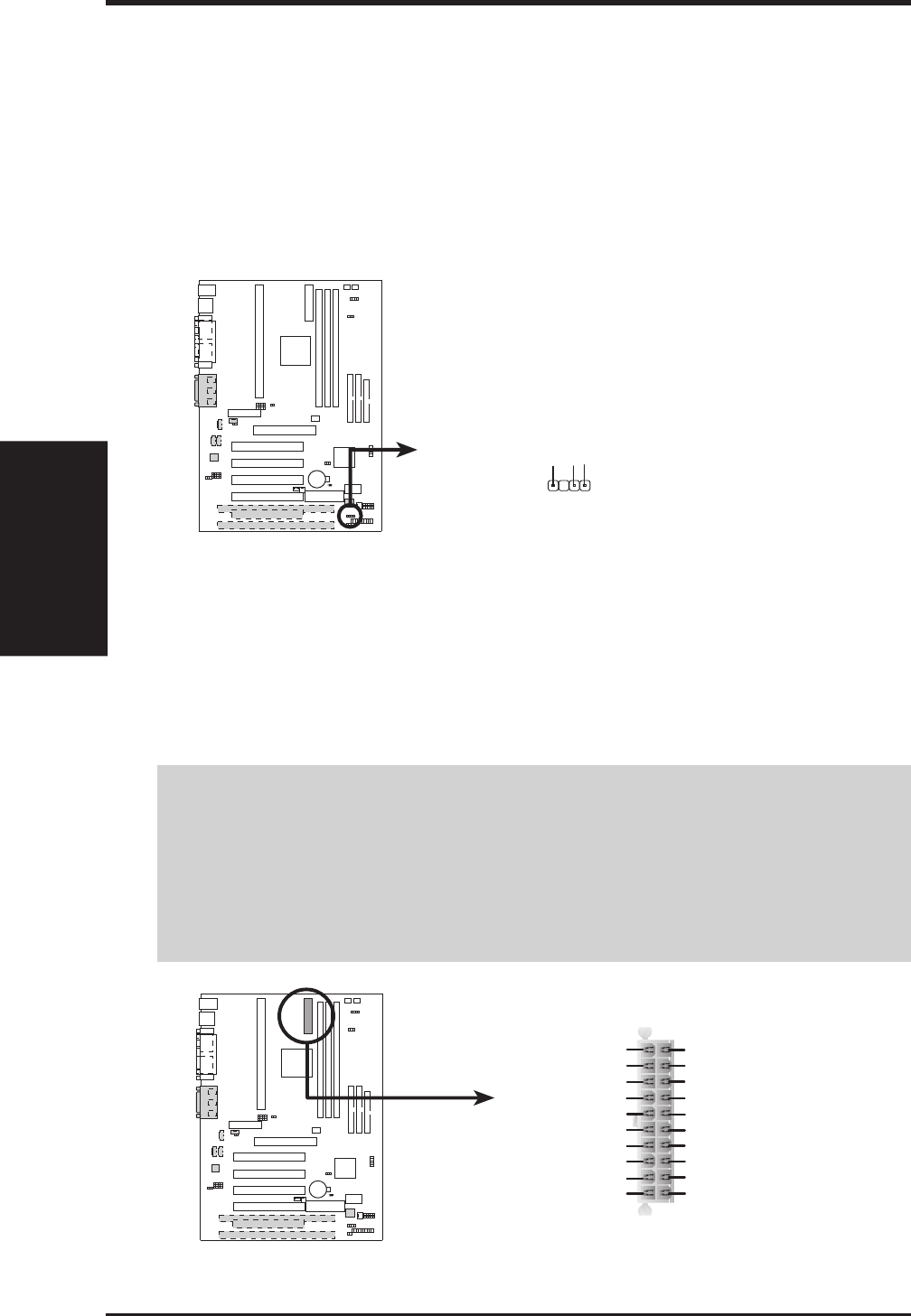
19) ATX Power Supply Connector (20-pin block ATXPWR)
This connector connects to an ATX power supply. The plug from the power sup-
ply will only insert in one orientation because of the different hole sizes. Find the
proper orientation and push down firmly making sure that the pins are aligned.
IMPORTANT: Make sure that your ATX power supply (minimum recommended
wattage: 200 watts; 235W for a fully-configured system) can supply at least 20
amperes on the +5-volt lead and 10mA on the +5-volt standby lead (+5VSB).
Your system may become unstable/unreliable and may experience difficulty in
powering up if your power supply is inadequate. For Wake-On-LAN support,
your ATX power supply must supply at least 720mA +5VSB.
010101
K7M
K7M ATX Power Connector
+3.3Volts
-12.0Volts
Ground
Power Supply On
Ground
Ground
Ground
-5.0 Volts
+5.0 Volts
+5.0 Volts
Power Good
+12.0Volts
+3.3 Volts
+3.3 Volts
Ground
+5.0 Volts
Ground
+5.0 Volts
Ground
+5V Standby
ATXPWR