


ASUS K7M User’s Manual 39
3. HARDWARE SETUP
Connectors
3. H/W SETUP
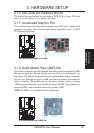
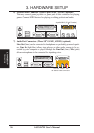
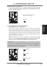
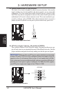
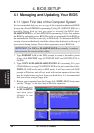
12) IDE Activity LED (2-pin IDE)
This connector supplies power to the cabinet’s IDE activity LED. Read and
write activity by devices connected to the Primary or Secondary IDE connectors
will cause the LED to light up.
K7M IDE Activity LED
TIP: If the case-mounted LED does not
light, try reversing the 2-pin plug.
IDELED
010101
K7M
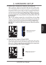
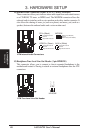
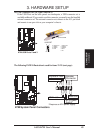
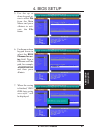
13) Power Supply, CPU, Chassis Fan Connectors
(3-pin PWR_FAN, CPU_, CHA_FAN)
These connectors support cooling fans of 350mA (4.2 Watts) or less. Orientate
the fans so that the heat sink fins allow airflow to go across the onboard heat
sink(s) instead of the expansion slots. Depending on the fan manufacturer, the
wiring and plug may be different. The red wire should be positive, while the
black should be ground. Connect the fan’s plug to the board taking into consid-
eration the polarity of the connector.
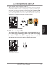
NOTE: The “Rotation” signal is to be used only by a specially designed fan with
rotation signal. The Rotations per Minute (RPM) can be monitored using ASUS PC
Probe (see section 6. SOFTWARE REFERENCE) or Intel LDCM Utility.
WARNING! The CPU and/or motherboard will overheat if there is no airflow
across the CPU and onboard heatsinks. Damage may occur to the motherboard
and/or the CPU fan if these pins are incorrectly used. These are not jumpers,
do not place jumper caps over these pins.
010101
K7M
K7M 12-Volt Cooling Fan Power
Chassis Fan Power
Power Supply Fan
CPU Fan Power
GND
Rotation
+12V
GND
Rotation
+12V
GND
Rotation
+12V