


ASUS K7M User’s Manual 41
3. HARDWARE SETUP
Connectors
3. H/W SETUP
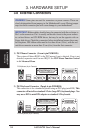
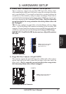
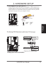
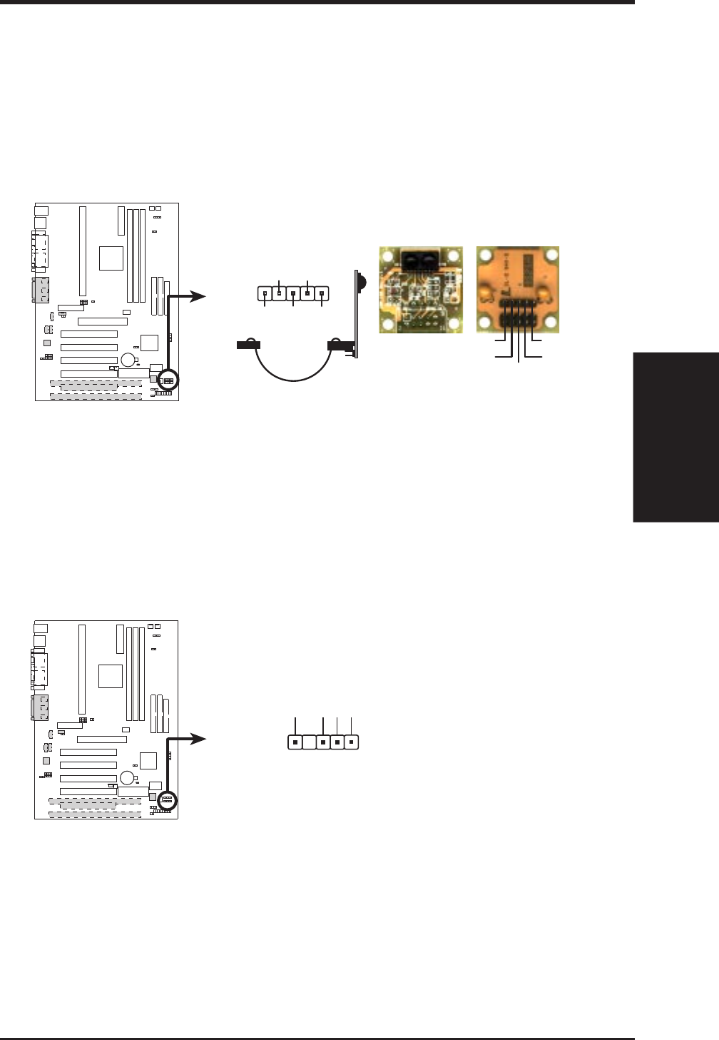
16) Serial Infrared Module Connector (5-pin IR)
This connector supports an optional wireless transmitting and receiving infrared
module. This module mounts to a small opening on system cases that support
this feature. You must also configure the setting through 4.4.5 Peripheral Setup
to select whether UART2 is directed for use with COM2 or IrDA. Use the five
pins as shown in Back View and connect a ribbon cable from the module to the
motherboard’s IR connector according to the pin definitions.
010101
K7M
K7M Infrared Module Connector
Front View
Back View
+5V
IRTX
IRRX
(NC)
GND
+5V IRRX IRTX
(NC) GND
IR
1
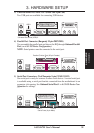
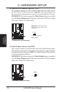
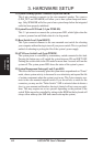
17) SMBus Connector (5-1 pin SMB)
This connector allows you to connect SMBus (System Management Bus) de-
vices. SMBus devices communicate by means of the SMBus with an SMBus
host and/or other SMBus devices. SMBus is a specific implementation of an I
2
C
bus, which is a multi-device bus; that is, multiple chips can be connected to the
same bus and each one can act as a master by initiating data transfer.
010101
K7M
SMBCLK
Ground
SMBDATA
+5V
1
K7M SMBus Connector
SMB