


44 ASUS K7M User’s Manual
3. HARDWARE SETUP
Connectors
3. H/W SETUP
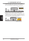
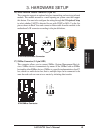
21) System Warning Speaker Connector (4-pin SPEAKER)
This 4-pin connector connects to the case-mounted speaker. Two sources
(LINE_OUT and SPEAKER) will allow you to hear system beeps and warn-
ings. Only SPEAKER will allow you to hear system beeps before the integrated
audio has been properly initialized.
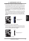
22) System Power LED Lead (3-1 pin PWRLED)
This 3-1 pin connector connects the system power LED, which lights when the
system is powered on and blinks when it is in sleep mode.
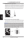
23) Reset Switch Lead (2-pin RESET)
This 2-pin connector connects to the case-mounted reset switch for rebooting
your computer without having to turn off your power switch. This is a preferred
method of rebooting to prolong the life of the system’s power supply.
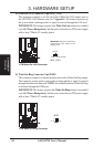
24) ATX Power Switch Lead (2-pin PWRSW)
The system power is controlled by a momentary switch connected to this lead.
Pressing the button once will switch the system between ON and SOFT OFF.
Pushing the switch while in the ON mode for more than 4 seconds will turn the
system off. The system power LED shows the status of the system’s power.
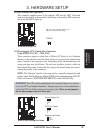
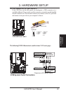
25) System Management Interrupt Lead (2-pin SMI)
This allows the user to manually place the system into a suspend mode or “Green”
mode, where system activity is decreased to save electricity and expand the life
of certain components when the system is not in use. This 2-pin connector con-
nects to the case-mounted suspend switch. If you do not have a switch for the
connector, you may use the “Turbo Switch.” SMI is activated when it detects a
short to open moment and therefore leaving it shorted will not cause any prob-
lems. This may require one or two presses depending on the position of the
switch. Wake-up can be controlled by settings in the BIOS but the keyboard will
always allow wake-up (the SMI lead cannot wake up the system).