


ASUS K7M User’s Manual 37
3. HARDWARE SETUP
Connectors
3. H/W SETUP
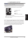
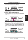
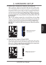
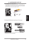
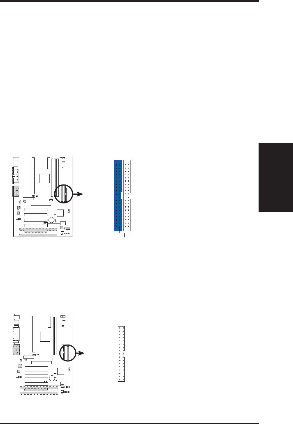
8) Primary (Blue) / Secondary IDE Connectors (Two 40-1pin IDE)
These connectors support the provided IDE hard disk ribbon cable.
After connecting the single end to the board, connect the two plugs at the other
end to your hard disk(s). If you install two hard disks, you must configure the
second drive to Slave mode by setting its jumper accordingly. Please refer to
your hard disk documentation for the jumper settings. BIOS now supports spe-
cific device bootup (see 4.4.1 Advanced CMOS Setup). (Pin 20 is removed to
prevent inserting in the wrong orientation when using ribbon cables with
pin 20 plugged).
TIP: You may configure two hard disks to be both Masters with two ribbon
cables – one for the primary IDE connector and another for the secondary IDE
connector. You may install one operating system on an IDE drive and another on
a SCSI drive and select the boot disk through 4.4.1 Advanced CMOS Setup.
IMPORTANT: UltraDMA/66 IDE devices must use a 40-pin 80-conductor
IDE cable.
010101
K7M
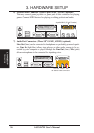
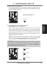
K7M IDE Connectors
NOTE: Orient the red markings
(usually zigzag) on the IDE
ribbon cable to
PIN 1
Primary IDE Connector
Secondary IDE Connector
PIN 1
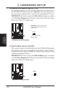
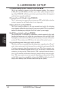
9) Floppy Disk Drive Connector (34-1pin FLOPPY)
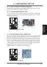
This connector supports the provided floppy drive ribbon cable. After connect-
ing the single end to the board, connect the two plugs on the other end to the
floppy drives. (Pin 5 is removed to prevent inserting in the wrong orienta-
tion when using ribbon cables with pin 5 plugged).
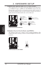
NOTE: Orient the red markings on
the floppy ribbon cable to
PIN 1
K7M Floppy Disk Drive Connector
PIN 1
FLOPPY
010101
K7M