


Chapter 1. Introduction
13
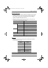
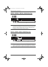
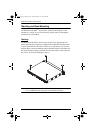
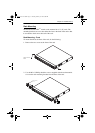
No. Component Description
1 Power Socket The power cable(s) plugs in here.
Note: For the KN2124v, KN2140v, KN4124v and the
KN4140v units, the top power socket corresponds to the left
power switch, and the bottom power socket corresponds to
the right power switch.
2 Power Switch This standard slide switch powers the unit on and off.
3 Secondary LAN
Port
The cable that connects the unit to the backup network
interface (10/100/1000 Mbps) plugs in here.
4 PON Port This connector is provided for a Power over the Net™
(PON) unit which allows servers attached to the KVM Over
the NET
TM
switch to be booted remotely over the net.
See Single Stage Installation, page 21, step 6 for
installation details. Contact your dealer for more information
regarding PON units.
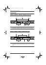
5 Grounding
Terminal
The wire used to ground the unit connects here.
6 Primary LAN
Port
The cable that connects the unit to the primary network
interface (10/100/1000 Mbps) plugs in here.
7 Modem Port For dial in connection should the unit be unavailable over
the network. See Single Stage Installation, page 21, step 7
for installation details.
8 Local Console
Port(s)
The unit can be accessed via a local console as well as over
the Net. The local console devices (keyboard, monitor and
mouse), plug in here. Any combination of USB and PS/2
keyboards and mice can be used.
Note: For the KN2124v, KN2140v, KN4124v and the
KN4140v units, use the 5-in-1 cable supplied with the
package to connect your console devices to the unit.
9 KVM Ports The Cat 5e cables that link the unit to the KVM Adapter
Cables (which connect to the servers), plug in here.
kn2124v-4132.book Page 13 Tuesday, January 12, 2010 5:08 PM