


Installation
38 ETEP Installation Guide
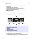
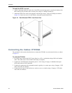
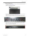
To install the ETEP in a rack:
1 Attach a mounting bracket to each side of the ETEP (near the front panel). Attach each bracket with
three small screws provided in the Accessory Kit, using a #1 Phillips screwdriver.
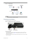
2 Attach the ETEP to the rack’s front supports with the large screws, using a #2 Phillips screwdriver
(Figure 24). Insert two screws in each bracket, using the top and bottom holes.
Figure 24 Rack Mounted ETEP, Front Panel View
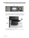
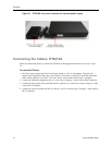
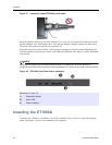
Connecting the Cables: ET0100A
The procedure in this section describes how to connect the ET0100A to your network devices, as shown
in Figure 25.
To cable the ET0100A:
1 For initial setup, connect the RS-232 port directly to a PC or workstation using a DB-9 null modem
cable. This cable can be removed after initial setup is complete.
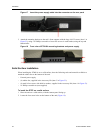
2 Connect the 10/100 Ethernet management port to a LAN using a Category 5 shielded twisted pair
(STP) cable with an RJ-45 connector.
3 Connect the remote port to the untrusted network, typically via a router port, using a Category 5 STP
cable with an RJ-45 connector.
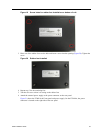
4 Connect the local port to the local device, such as a server or switch, using a Category 5 STP cable
with an RJ-45 connector.