


Installation
46 ETEP Installation Guide
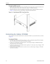
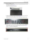
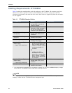
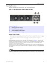
Figure 33 Dual power supplies on the ET1000A rear panel
To power on the ET1000A:
1 On the appliance’s rear panel, plug the power cords into the power receptacles for each power supply.
2 Attach the opposite end of the first power cord to a power source. Attach the second power cord to a
a power source on a different circuit. The power supply status LED illuminates when power is
applied.
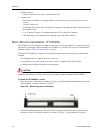
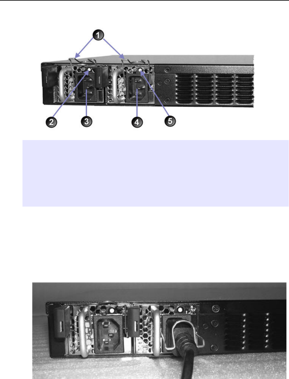
3 After the power cords are plugged in, secure the cords using the clips on the rear of the unit.
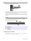
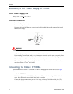
Figure 34 The power cord for power supply # 1 is secured with a clip
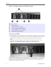
When the appliance powers up, all of the front panel LEDs illuminate (see Figure 35). The Alarm LED
illuminates briefly and the diagnostic code LED displays 88 to verify that the diagnostic display segments
are functioning. The power LED remains lit until the unit is powered off. The Power Supply LEDs
illuminate for each operational power supply.
Elements of Figure 33:
1) Power cord clips
2) Status LED for power supply 2
3) Power receptacle for power supply 2
4) Power receptacle for power supply 1
5) Status LED for power supply 1