


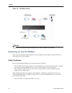

Installing the ET10000A
ETEP Installation Guide 51
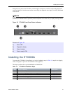
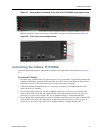
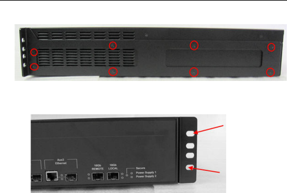
Figure 37 Each bracket is attached to the side of the ET10000A using eight screws
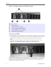
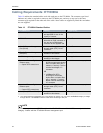
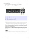
3 Attach the mounting brackets to the rack’s front support with the large #10-32 screws, using a #2
Phillips screwdriver. Insert two screws in each bracket, using the top and bottom holes (Figure 38).
Figure 38 Front view of mounting brackets
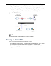
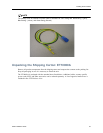
Connecting the Cables: ET10000A
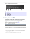
Follow the instructions below to connect the ET10000A to the appropriate network devices (see Figure
39).
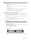
To cable the ET10000A:
1 For initial setup, connect the RS-232 port directly to a PC or workstation. Using the null modem cable
supplied by Black Box, insert the RJ-45 connector in the RS-232 port and connect the DB-9 female
connector to your PC. This cable can be removed after initial setup is complete.
2 Connect the Ethernet management port to a LAN using a Category 5 shielded twisted pair (STP)
cable with an RJ-45 connector.
3 Plug an SFP Gigabit transceiver into the ET10000A remote port. If you are using an optical SFP,
insert the fiber cable in the SFP and connect the other end to the untrusted network, typically via a
router port. If you are using a copper SFP, use an shielded Category 5 straight through cable.
4 Plug a second SFP Gigabit transceiver into the ET10000A local port. If you are using an optical SFP,
insert the fiber cable in the SFP and connect the other end to the local device, such as a server or
switch. If you are using a copper SFP, use an shielded Category 5 straight through cable.