


Installing the ET10000A
ETEP Installation Guide 53
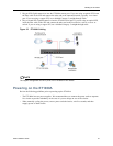
Power-Up Procedure
Follow the instructions in this section to safely apply power to the ET10000A.
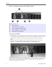
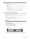
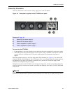
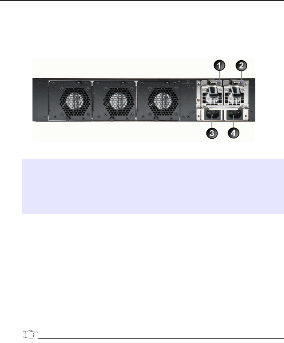
Figure 40 Dual power supplies on the ET10000A rear panel
To power on the ET10000A:
1 On the appliance’s rear panel, plug the power cords into the power receptacles for each power supply.
2 Attach the opposite end of the first power cord to a power source. Attach the second power cord to a
a power source on a different circuit. The power supply status LED illuminates when power is
applied.
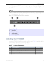
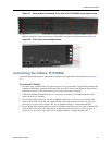
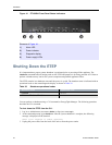
When the appliance powers up, all of the front panel LEDs illuminate (see Figure 41). The Alarm LED
illuminates briefly and the diagnostic code LED displays 88 to verify that the diagnostic display segments
are functioning. The power LED remains lit until the unit is powered off. The Power Supply LEDs
illuminate for each operational power supply.
During the boot process the ET10000A cycles through its startup tests, and the corresponding diagnostic
codes are displayed. After the tests execute successfully, the diagnostic code display is solidly illuminated
with code 00.
NOTE
During the boot process the ET10000A discards all traffic on its data ports. Once the appliance is
operational, the default mode of operation passes all packets in the clear until you deploy security policies.
Elements of Figure 40:
1) Status LED for power supply 2
2) Status LED for power supply 1
3) Power receptacle for power supply 2
4) Power receptacle for power supply 1