


Chapter 3: VLAN Configuration
3-38 802.1Q VLAN User’s Guide
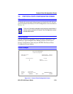
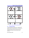
15. On the 802.1Q VLAN Main Menu screen, use the arrow keys to
highlight the DEVICE VLAN CONFIGURATION menu item.
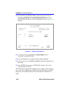
Press ENTER. The Device VLAN Configuration screen, Figure 3-14,
displays.
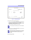
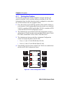
Figure 3-14 Walkthrough Stage Four
16. Use the arrow keys to highlight the Admin Status field of
VLAN ID 2, the TEST VLAN.
17. Press the SPACE bar to toggle the field to display Enabled.
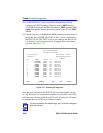
18. Use the arrow keys to highlight the SAVE command at the bottom of
the screen.
19. Press ENTER. The message “SAVED OK” displays. The switch
activates the new VLAN.
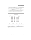
This effectively completes the configuration of a single VLAN, assigning
it to a port, and configuring the switch to forward the frames received on
that port to be forwarded with the VLAN information included in the
frame.
Firmware Revision: XX.XX.XX
Device/VLAN Configuration
25993-12
Module Type: xxxxx-xx
BOOTPROM Revision: XX.XX.XX
6C105 LOCAL MANAGEMENT
Slot Number: xx
RETURN
EXIT
Forward Default VLAN Out All Ports: [NO]
VLAN ID
1
2
FID
1
2
VLAN Name
DEFAULT VLAN
TEST VLAN
Admin Status
[Enabled]
[Enabled]
VLAN ID: 1 FID: 2 VLAN Name: DEFAULT VLAN [ADD]
SAVE