


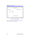
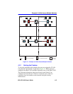
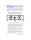
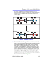
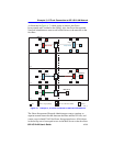

Example 2, VLANs Across Multiple Switches
802.1Q VLAN User’s Guide 4-7
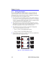
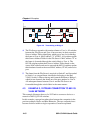
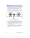
Switch 2
Switch 2 is set as follows:
1. Two VLANs are added to the list of VLANs using the Device/VLAN
Configuration screen and assigned to a FID. In this example they are
as follows:
• VLAN ID 2, FID 2, with a VLAN Name of Red
• VLAN ID 3, FID 3, with a VLAN Name of Blue
2. A Port VLAN ID is assigned to each port (1 and 3) as follows using
the Port Assignment screen:
• Port 1, VLAN ID: 223 for the Blue VLAN
• Port 3, VLAN ID: 222 for the Red VLAN
These settings change the configuration of the switch, so that Port 1 is
part of Blue VLAN, Port 3 is part of Red VLAN, and both are set as
frame type of untagged.
3. Port 2 is configured as a 1Q Trunk port as follows using the Port
Assignment Configuration screen:
• Port 2, Port Mode: 1Q Trunk
Port 2 is set as an 802.1Q Trunk port, which makes its Port VLAN List
contain all VLANs and sets all frames forwarded out this port as
tagged frames. This completes the transmission path between
Switch 4 and Switch 2.