


Chapter 4: Examples
4-12 802.1Q VLAN User’s Guide
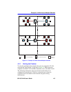
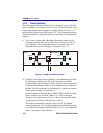
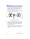
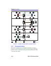
4.3.1 Solving the Problem
Much of the existing network configuration can remain as it was for
Example 2, VLANs Across Multiple Switches. However, the Forward
Default VLAN Out All Ports must be set to YES on Switch 4 and 2, and a
new 1Q Trunk port must be activated and configured on Switch 2. There
are no other real changes to the network above the first floor.
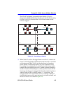
Switch 4
Switch 4 is set as follows:
1. The Forward Default VLAN Out All Ports is set to YES using the
Device/VLAN Configuration screen. This adds the Default VLAN to
the Port VLAN List of every switch port and all VLANs become
members of FID 1. This allows all traffic received from the mail server
via Switch 2 and Switch 1 to be received and classified to the Default
VLAN of Switch 4.
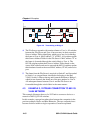
Switch 2
Switch 2 is set as follows:
1. The Forward Default VLAN Out All Ports is set to YES using the
Device/VLAN Configuration screen. This adds the Default VLAN to
the Port VLAN List of every switch port and all VLANs become
members of FID 1.
2. The port mode of Port 4 is set using the Port Assignment screen:
• Port 4, Port Mode: 1Q Trunk
This causes Port 4 to be set as an additional 802.1Q Trunk port, which
makes its Port VLAN List contain all VLANs, and all frames
forwarded out this port are forwarded as tagged frames.
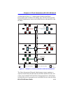
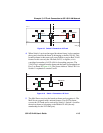
Switch 1
Switch 1 needs to be added to the network backbone to handle traffic from
the Green Incorporated network and the mail server. To accomplish this
Switch 1 is configured as follows:
1. One VLAN is added to the list of VLANs in the Device/VLAN
Configuration screen. In this example, Switch 1 is set as follows:
• VLAN ID 4, FID 4, with a VLAN Name of Green